 Figure 1: RTDMS version 1.0
Recent advancements in embedded computing technology have enabled a new generation of smaller and faster internet-of-things (IoT) devices. In research and development (and often in military contexts), the acronynm SWaP-C is used in reference to optimizing the Size, Weight, Power, and Cost of pysical devices, systems, and programs. The convergence of allied technologies such as edge computing, scalable cloud services, AI/ML algorithm advancement, and ubiqutious high bandwidth network availability (e.g., 5G), have led to an evolving ecosystem that offers a cost-effective, performant, scalable, and resilent approach to solving traditionally hard computational challenges. Although new technology offers advantages over traditional methods, there are also unintended consequences that introduce new risks. The adoption of IoT technology into military and commercial environments has been stifled due to the increased security risks and interoperability challenges that result from lacking standards and propritary vendor systems that span the major pedigrees of device types, hardware features, and supported network communication protocols. The high degree variability across the major device types has significantly increased the complexity of reasoning about security, conformance, interoperability, and compliance testing.
Figure 1: RTDMS version 1.0
The objective of this is to enable cyber security analysts and systems engineers to develop the architectural awareness to reason critically about the design, security, and resiliency of IoT systems. IoT systems consist of hetergenous parts, and is therefore important that analysts have a holistic understanding of the underlying architecure. This repository describes an active learning project that leads the student through the end-to-end scenaro to design and implementation of a (“Smart”) IoT prototype that provides remote datacenter condition monitoring, automated temperature regulation, and automated operator alerting. The student will gain a more complete understanding by designing and implementing an IoT systemfrom scratch, beginning with prototyping the basic device hardware, developing the essential software to drive the device, and the code required to process telemetry deployment and executed in the Cloud. At each layer of the design, a critical security analysis/assessment should be performed to identify and document potential vulnerabilities. A mitigation strategy should be developed and implemented for each identified case.
Information technology (IT) infrastructure is one of the most important assets to data centric environment. If IT equipment such as servers, firewalls, routers, switch panels and related systems were to overheat, it could significantly impact the performance, availability, and the reliability of critical information systems, potentually resulting in grave financial damage and even loss of life. The application of new IoT technology and with the use of Cloud services can be used to achieve a lightweight, cost-effective solution that minimizes costs and overhead by automating certain datacenter maintenance operations such montoring and regulating temperature conditions.
The RDTMS (v1.0) is intended to be prototyped using the Raspberry PI (RPi) SBC (single board computer), version 2 or greater. The purpose is to developed a "smart" HVAC system to monitor temperature and humidity conditions, and automatically activate/deactivate an external HVAC unit when sensed operating conditions exceed specified thresholds. A LCD character display is used indicate HVAC operation (ON/OFF) status. The system will automatically dispatch a recorded phone call or text message to alert maintenance operators when conditions exceed specified threshholds. If-This-Then-That (IFTTT) automation service is integated using a webhook exposed from an Azure function to facilite making phone call, sending the text message, or sending an email. A downloadable Cloud-hosted (PaaS) web application will deployed to the Azure Cloud, and used to provide maintenance operators with a real-time visualization and telemetry monitoring capability that can be viewed using a desktop PC or mobile device.
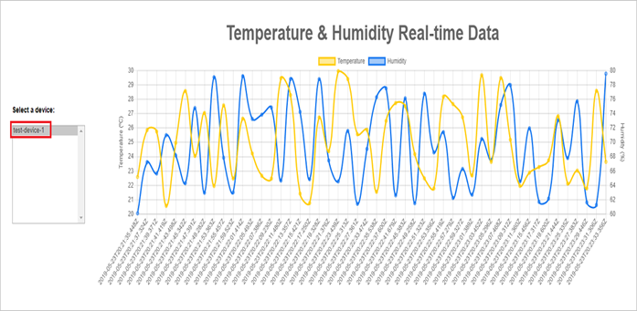 Figure 2: Azure Cloud-Hosted (PaaS) TelemeMonitoring Web Application
This project is about the design and implementation of a robust prototype solution for the sample problem above.
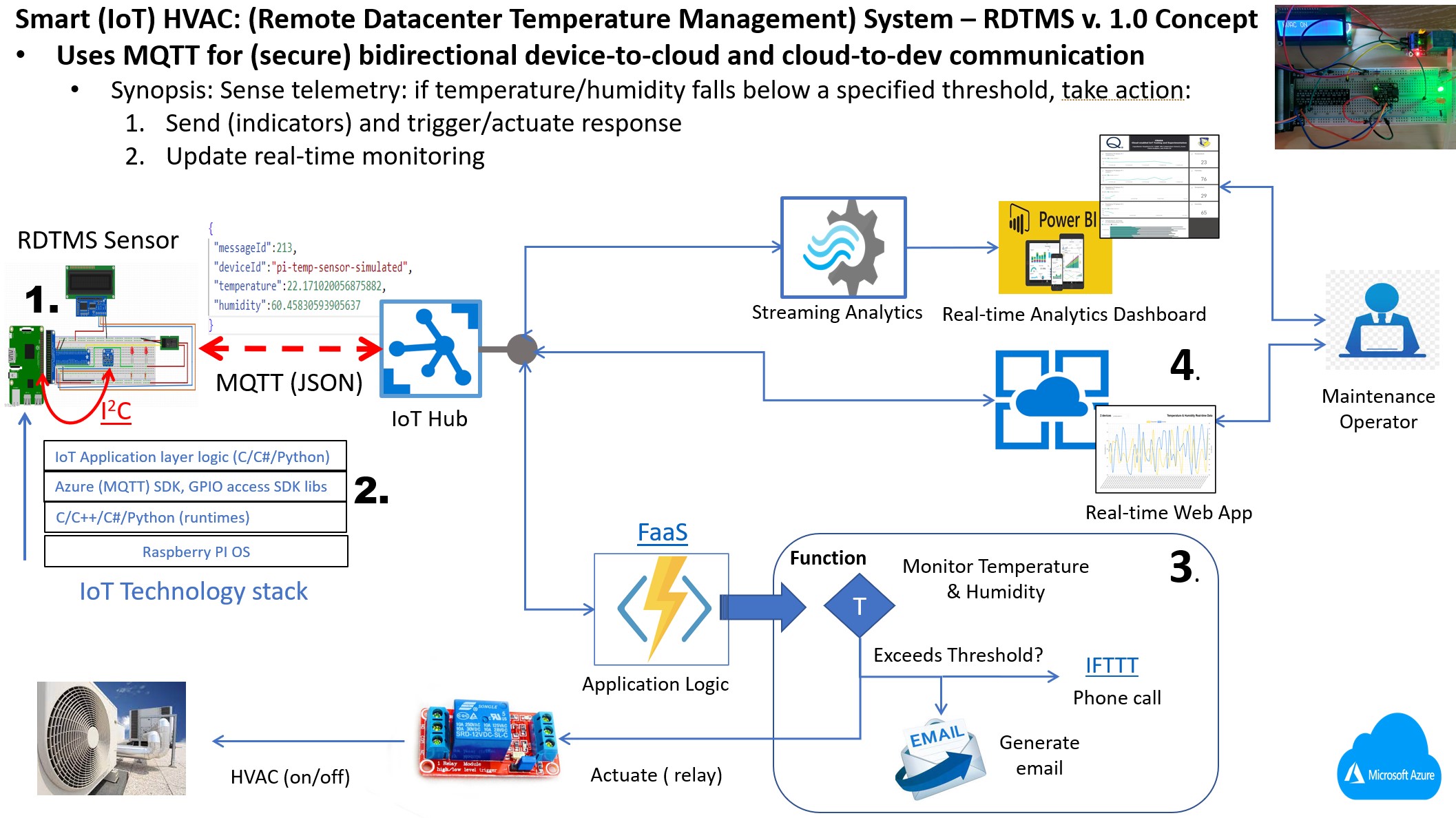
Figure 3: RTDMS Concept
Using the concept illustrated in Figure 3, the implementation for the "Smart" HVAC prototype can be divided into four (4) basic tasks: :
Security and Resilience: “Security by Design” is a set of principles and strategies applied to design of software systems and applications that have been designed to be foundationally secure. It is imperative to think critically about high-level design choices with best practice awareness. Architectural modularity is a key to ensuring a software system is robust, extensible, and maintainable to support requirements for change, as well as for enabling efficient procedures for correcting identified flaws (bugs), security vulnerabilities, and unforeseen risks that can arise as the system evolves over its lifecycle.
A commonly held conceptual architecture framework for testing and assessing IoT devices for security and resiliency is illustrated as follows:
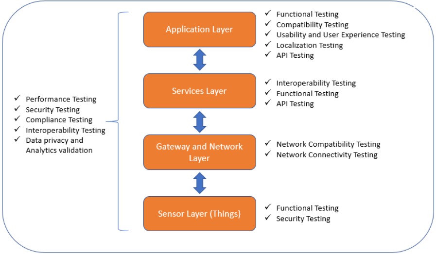 Figure 4: Conceptual architecture framework for testing and assessing IoT devices
 As Figure 4 depicts, the functionality comprising IoT devices generally maps into 4 layers:
As a security testing framework, each respective layer represents a conceptual mapping the device architecture functionality to specific testing types that should be performed. Compare this framework to the RTDMS concept architecture depicted in Figure 4 (above). From Figure 3, and determine how the RTDMS functionality maps into the testing framework.
Device (Hardware) requirements: RPi dev board (versions 2,3, and 4 suffice), and full-size breadboard consisting of the following electronic components:
The electronic components connect to the RPi through the 40-pin general purpose input/output (GPIO) header. The GPIO supports low-level pin access and serial bus protocols for communicating (input and output) between the RPi device and external electronic components.
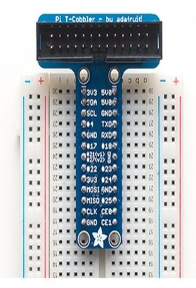 Figure 5: GPIO expansion (TCobbler)
The breadboard shown in Figure 5 (above) is paired with a GPIO expansion board to simplify prototyping with GPIO header. This particular GPIO expansion board is often called a GPIO breakout, or simplify a T-Cobbler Plus connection.
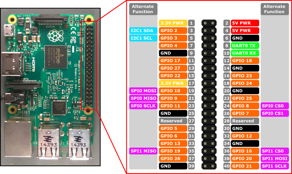 Figure 6: GPIO Header Close Up
RPi supports multiple pin numbering schemes (GPIO, BOARD) that determined how pins are identified and addressed by in source code. This RTDMS project will use the GPIO scheme. View the following reference for more detail on RPi supported pin number schemes: https://learn.sparkfun.com/tutorials/raspberry-gpio/gpio-pinout Figure 6 (above) provides a close up view of the the GPIO header. RPi supports serial bus protocols including I2C and SPI through the GPIO header.
 Note: Inter-Integrated Circuit (I2C) is a well-known serial bus protocol for connecting
integrated circuits (such as the BME280 temperature sensor) over low speed, short-distance serial communication.
I2C is straight forward to use since it requires only two GPIO pins to operate: SDA (for data
transfer), and SCL (for carrying the clock signal). I2C and the similar serial peripheral interface
(SPI) protocol are commonly used in embedded device applications such as gateways and home routing devices, as
well as industrial/commercial devices for integrated circuit communication. See the following URL for additional
detail on these protocols : https://learn.sparkfun.com/tutorials/i2c/all
Note: Inter-Integrated Circuit (I2C) is a well-known serial bus protocol for connecting
integrated circuits (such as the BME280 temperature sensor) over low speed, short-distance serial communication.
I2C is straight forward to use since it requires only two GPIO pins to operate: SDA (for data
transfer), and SCL (for carrying the clock signal). I2C and the similar serial peripheral interface
(SPI) protocol are commonly used in embedded device applications such as gateways and home routing devices, as
well as industrial/commercial devices for integrated circuit communication. See the following URL for additional
detail on these protocols : https://learn.sparkfun.com/tutorials/i2c/all
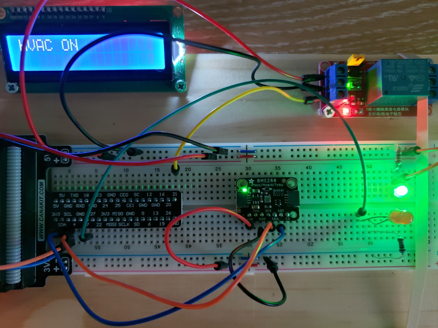
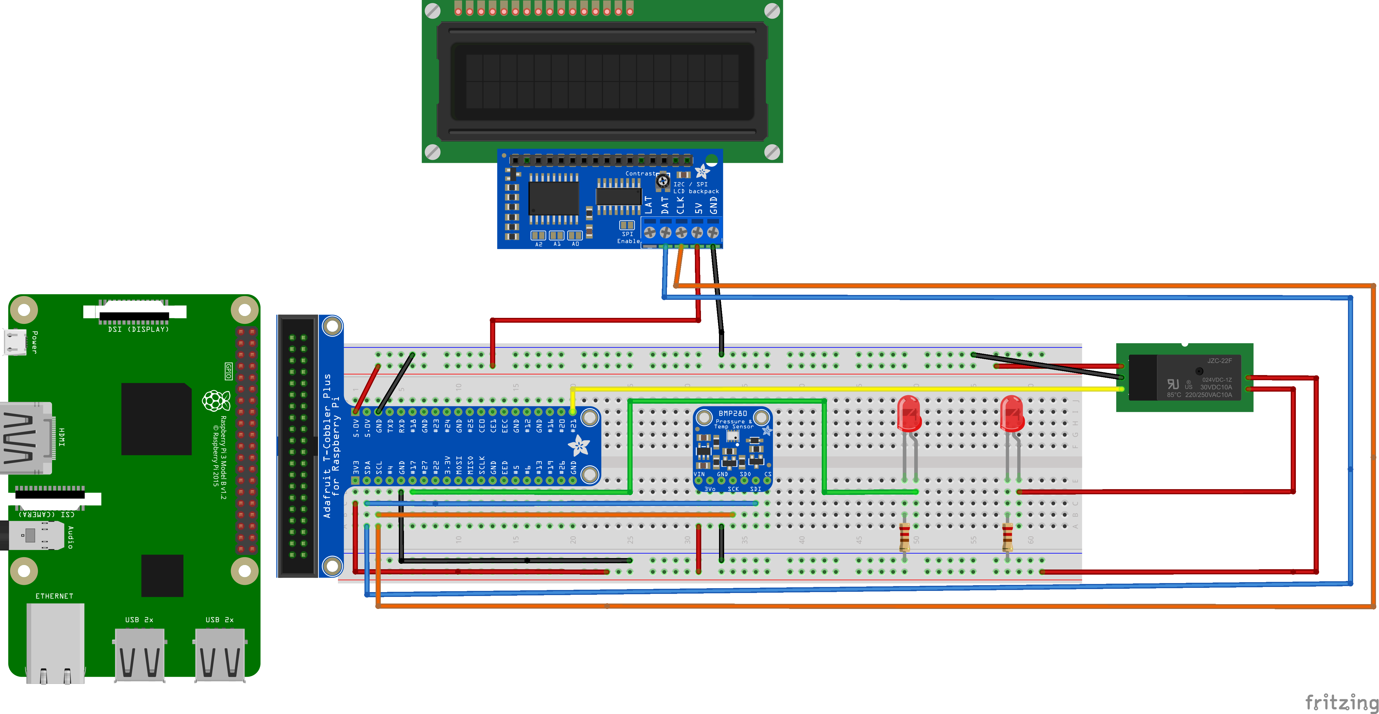 Figure 7: RTDMS Device Sketch
Complete the steps (1-14) below to construct the device: The finished prototype should closely resemble Figure 7 (above).
Note:the following tutorial (URL below) by Cam Soper is an excellent primer for understanding the
basic breadboard prototyping concepts and code, with illustrations for connecting the BME280 sensor to the GPIO
header:
https://learn.microsoft.com/en-us/training/modules/create-iot-device-dotnet/2-construct-iot-hardware
 Warning: care must be taken with connecting devices to the GPIO header. Improper electrical connections
can
permanently damage the Raspberry Pi
Warning: care must be taken with connecting devices to the GPIO header. Improper electrical connections
can
permanently damage the Raspberry Pi
 Danger: The RTDMS sketch (above) is shown with an LED acting as a stand-in for the HVAC system. This is
primarily
to test the application logic during development. The completed prototype uses the relay to control a separate,
high-voltage circuit to power external devices (the HVAC unit). It is important to ensure that the
relay is properly connected to the high-voltage side! Incorrect connection of the relay to a 120v AC
outlet can
result in a dangerous electrical shock and/or a fire! The mentor will assist in ensuring the
relay is properly
connected for activating the HVAC unit. The figure below illustrates the completed RTDMS prototype with the
connection for the 120V AC power outlet.
Danger: The RTDMS sketch (above) is shown with an LED acting as a stand-in for the HVAC system. This is
primarily
to test the application logic during development. The completed prototype uses the relay to control a separate,
high-voltage circuit to power external devices (the HVAC unit). It is important to ensure that the
relay is properly connected to the high-voltage side! Incorrect connection of the relay to a 120v AC
outlet can
result in a dangerous electrical shock and/or a fire! The mentor will assist in ensuring the
relay is properly
connected for activating the HVAC unit. The figure below illustrates the completed RTDMS prototype with the
connection for the 120V AC power outlet.
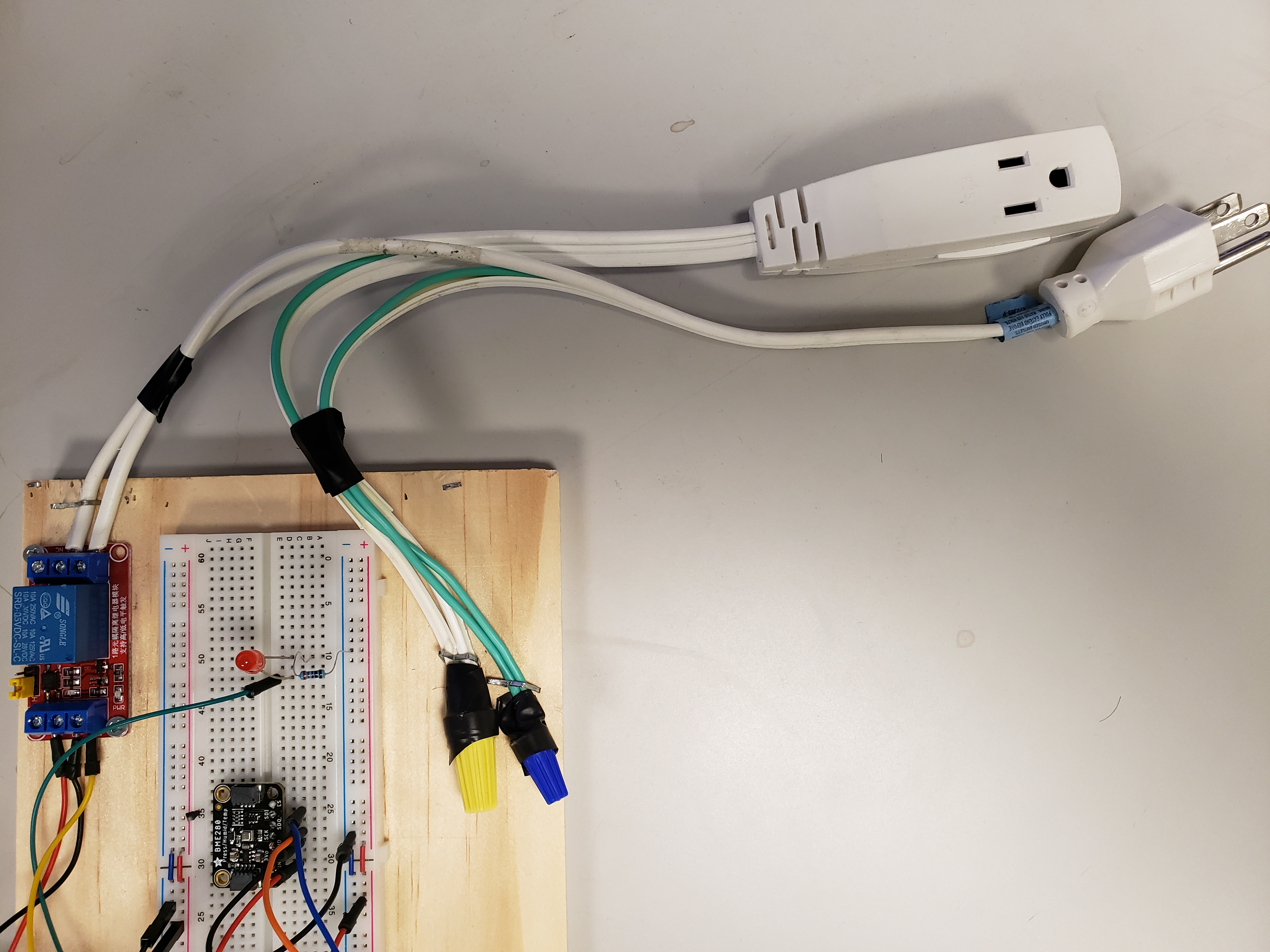 Figure 8: RTDMS prototype with 120v AC Outlet Connection
Raspberry Pi Setup and Configuration
Refer to the following URL, follow the documentation to download and install the Raspberry Pi Imager to a computer with an SD Card reader. Insert the SD card into the computer: https://www.raspberrypi.com/software/operating-systems/ The Imager will provide an option to choose "Rasperry Pi OS (other)". Select Raspberry Pi OS (64-bit Debian Bullseye) Pi Desktop as shown in below.
Note: You can use the 32-bit version of the Raspberry OS, but the 64-bit version is recommended.
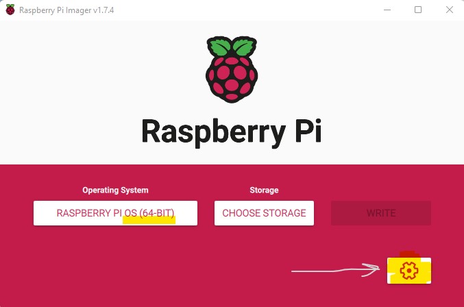
Figure 9: Raspberry PI Imager: Use cog on the right to specify required configuration settings
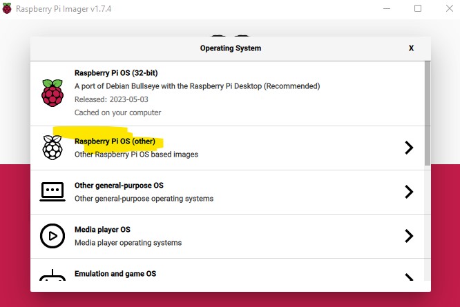
Figure 10: Select Raspberry Pi OS (other)
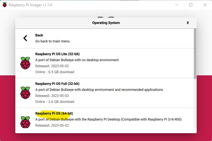
Figure 11: Use the 64-bit version
Complete the Raspberry Pi OS Configuration
Upon completing Raspberry Pi OS isntallation, open a terminal, and run the raspi-config command. Ensure the following services are enabled:
Test that the BME280 sensor and the LCD character display are configured properly for I2C bus communication:
Use the "i2cdetect" command as discussed in the following URL, to scan the I2C bus. The BME280 and LCD character display addresses should be displayed as 0x77 for the BME280, and 0x27 for the LCD character display. If no addresses appear in the scan (or only one address) then either the circuit configuration is incorrect, and/or potentially the BME280 sensor working properly. https://learn.adafruit.com/scanning-i2c-addresses/raspberry-pi
The RTDMS driver is the code that runs on the physical device. This includes the code for reading the BME280 (TPH) sensor data over the I2C bus, and packaging the data as telemetry to dispatch to the Cloud. As you will see below, the majority of the code has been provided. Your job is understand and complete each of the code sections as described. The project was prepared on Ubuntu 22.04 host, developed with the C# programming and .Net 6.0 SDK environment using the standard .Net IoT NuGet packages. Visual Studio (VSCode) editor with appropriate extensions is the recommended code editor. The Raspberry 3 single board computer (SBC) with ARM-64bit CPU, latest version of Raspberry Pi OS (Debian Linux distro) was selected the target platform for the RDTMS prototype.
RTDMS prototype transmits temperature and humidity telemetry to the Azure(IoT Hub) Cloud service using Message Queuing Telemetry Transport (MQTT) protocol. You will will need an Azure Cloud subscription. Refer to the following URL, use your university or school email to sign up a $100 Azure credit (good for 12 months): https://azure.microsoft.com/en-us/free/students/
Refer to the following URL to create an Azure IoT Hub Service (using the free tier), and register a new IoT device. Name the device the "RTDMS_dev1".
Copy the device the primary connection string, you will need to configure the appsettings.json configuration file in thge next section. The connection string is needed for authenticating the RTDMS device, and the Azure Cloud (IoT Hub service). https//learn.microsoft.com/en-us/azure/iot-hub/iot-hub-raspberry-pi-web-simulator-get-started#create-an-iot-hub
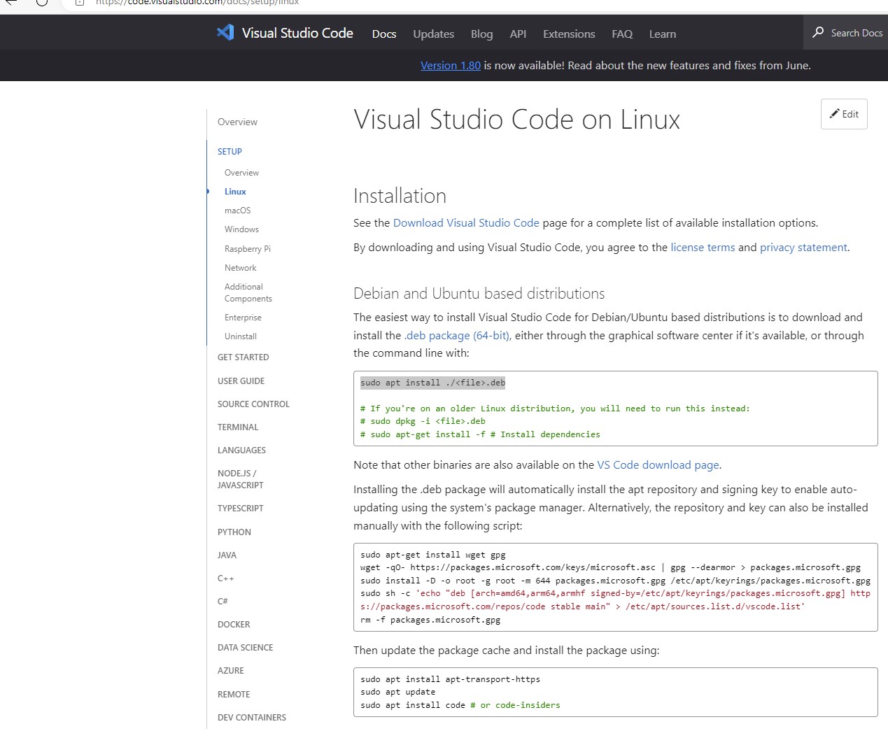
Follow the instructions to Download Visual Studio Code (VSCode) editor for Linux: https://code.visualstudio.com/docs/?dv=linux64_deb
VScode issue: In some instances, with recent versions VSCode (v1.79+) don't operate correctly with Azure Functions
Extension (needed later) on
Ubuntu 22.04 (i.e. the "+" create workspace, function projects doesn't appear in the extension window). If you experience
this issue, the interim fix is to install a previous VSCode version 1.78 (April 2023) as illustrated:
Download VSCode 1.78
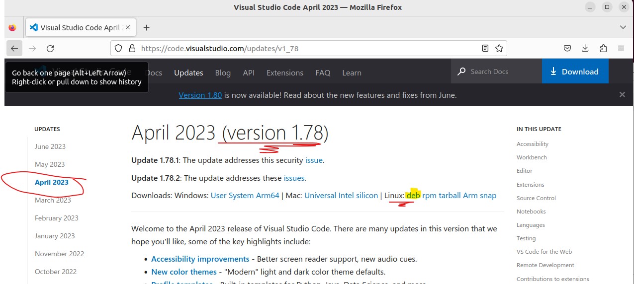
VSCode: Install version 1.78 to resolve errors with Azure Functions Extension
      sudo apt install ./.deb
      # If you're on an older Linux distribution, you will need to run this instead:
       # sudo dpkg -i .deb
       # sudo apt-get install -f # Install dependencies
Start VSCode and install the official (Microsoft) C# language extension as illustrated (below):
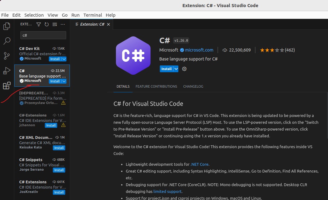 Official C# VSCode extension
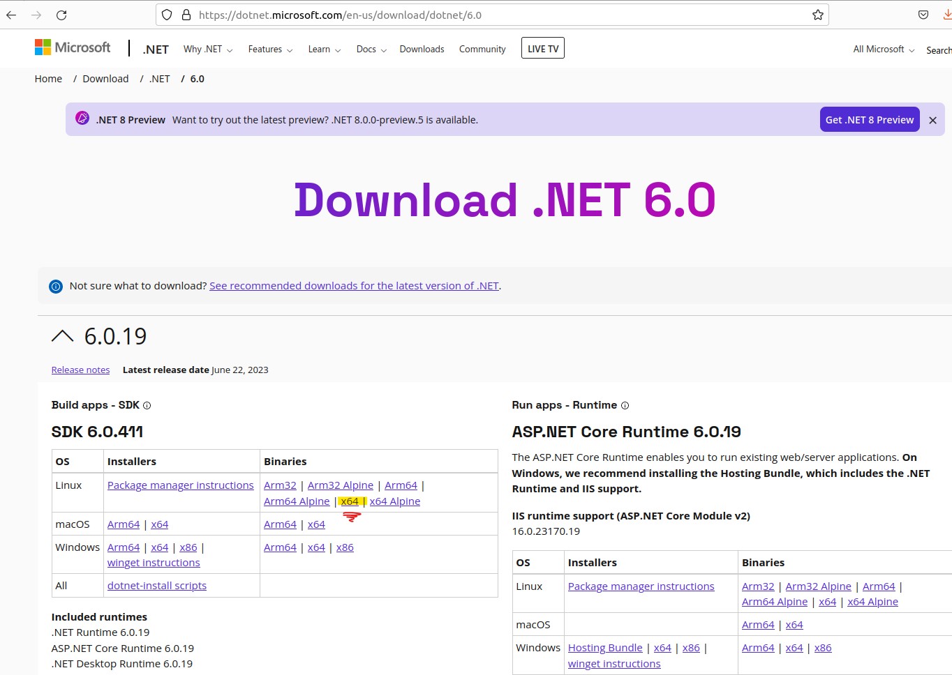 Dotnet 6.0: https://dotnet.microsoft.com/en-us/download/dotnet/6.0
Extract the downloaded file to $HOME/dotnet folder and set using export to execute the dotnet commands from current session:
Note: The command below illustrates use with dotnet sdk version: "dotnet-sdk-6.0.411". You will need to
substitute
with your downloaded version of the dotnet SDK.
            # note: substitute vers. 6.0.411 for other downloaded .Net SDK versions
            mkdir -p $HOME/dotnet && tar zxf dotnet-sdk-6.0.411-linux-x64.tar.gz -C $HOME/dotnet
            export DOTNET_ROOT=$HOME/dotnet
            export PATH=$PATH:$HOME/dotnet

            # Run nano editor to edit the .bashrc
            nano ~/.bashrc

            # Copy the commands below to the .bashrc
            export DOTNET_ROOT=$HOME/dotnet
            export PATH=$PATH:$HOME/dotnet

            # Run this command so the terminal session will use the new settings
            source ~/.bashrc
Verify the SDK is installed, by listing the SDKs installed on the host, using the terminal command:
dotnet --list-sdks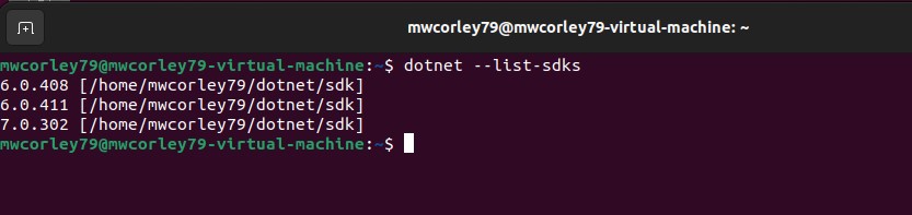
List dotnet SDKs installed
Open terminal, and use the dotnet CLI (command line interface) to run the command below.
Note about solutions and projects: The .Net solution is container for .Net projects. Notice there is currently one console
project (RTDMS-driver), and one library project (TelemModel). Both projects are added to the RTDMS-V1 solution.
The "dotnet new console" command creates a project configuration that builds (compiles) to a .Net executable
assembly (an .exe) file. Executable files are command line programs intended to be run
from the "console" (the terminal/shell window). Library projects by contrast, are not executed directly
(such as the TelemModel project). Libray projects are compiled to dynamic link library (.dll) assemblies,
and linked to console (executable) projects during compilation (statically), or (dynamically) at runtime.
In most cases, library projects contain code that intended to be shared (reused) by multiple projects.
            # Open command termninal, navigate to the home (~) folder and make a projects folder
            cd ~
            mkdir projects && cd projects

            # 1. Create the solution (sln), and make that the current folder:
            dotnet new sln -o RTDMS-V1
            cd RTDMS-V1

            # 2. Create the RTDMS-driver project:
            dotnet new console -o RTDMS-driver --use-program-main

            # 3. Create a class library called: TelemModel:
            dotnet new classlib -o TelemModel

            # 4. Add the RTDMS-driver project to the solution (sln):
            dotnet sln add RTDMS-driver/RTDMS-driver.csproj

            # 5. Add the Telemetry project to the solution (sln):
            dotnet sln add TelemModel/TelemModel.csproj

            # 6. Navigate to the RTDMS project folder:
            cd RTDMS-driver
            # Add the TelemModel project reference:
            dotnet add RTDMS-driver.csproj reference ../TelemModel/TelemModel.csproj

            # Add the following NuGet packages to the RTDMS-driver project:
            # IoT Gpio) package:
            dotnet add package System.Device.Gpio

            # IoT (Bindings) package:
            dotnet add package IoT.Device.Bindings

            # JSON config provider package:
            dotnet add package Microsoft.Extensions.Configuration.Json

            # config binder package:
            dotnet add package Microsoft.Extensions.Configuration.Binder

            # Azure IoT Hub device SDK package to connect devices to Azure IoT Hub:
            dotnet add package Microsoft.Azure.Devices.Client
The RTDMS-driver is a Linux Executable program that implements device functionality on a Raspberry Pi, using the services of various software artifacts:
Note on the C# .Net IoT (NuGet) Library packages:
                # Nativate to the RTDMS_V1 solution (sln) folder
                cd ~/projects/RTDMS-V1

                # open VScode from the sln folder
                code .
As illustrated by the VSCode screenshot below: Create a subfolder named src under the RTDMS-driver project folder:
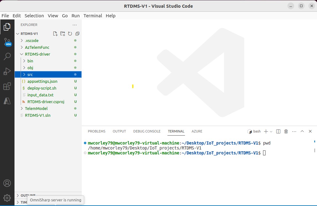 VSCode: RDTMS Solution folder
Under the "RDTMS_driver/src" folder, create the following C# code (.cs) files, and copy the code content as specifed for each file.
1. Move the existing Program.cs file in "RDTMS_driver/" to the "RDTMS_driver/src" folder, and replace the contents of the file with the code shown below:
            // Description: Interim (version 1) IoT bootcamp development project (Remote Data Center Monitoring) prototype
            // Skill Level: university engineering or comp sci ( sophomore and higher)

            // This file is main .exe (client) RDTMS driver entry point
            using Microsoft.Extensions.Configuration;

            namespace viceroy
            {
                public class RTDMS_Driver_Exec
                {
                    static void Main(string[] args)
                    {
                        // Build a config object, using JSON providers.
                        // https://learn.microsoft.com/en-us/dotnet/core/extensions/configuration
                        IConfiguration config = new ConfigurationBuilder()
                        .AddJsonFile("appsettings.json")
                        .Build();

                        Console.WriteLine("\t** RTDMS IoT driver version 1.0 ** ");
                        // instantiate the RTDMS driver object
                        // Note: the using ensires the that "dispose is called when the object
                        // goes out of scope. Dispose ensures that plaform resources are freed, not waiting
                        // for the garbage collector
                        using RTDMS_Driver driver = new RTDMS_Driver();

                        Console.WriteLine("\t\tHVAC using pin {0}", driver.Settings.HVACPin);
                        Console.WriteLine("\t\tLED using pin {0}", driver.Settings.LEDPin);

                        // start the RDTMS driver (starts the main driverTask)
                        driver.Start();

                        // stop the RTDMS driver (this blocks until the driverTask completes when the user exits the menu )
                        driver.Stop();
                    }
                }
            }
2. Create a new .cs file called: RTDMS.cs in "RDTMS_driver/src". Copy and Paste the code below and save the file. RTDMS.cs implements the primary RTDMS-driver functionality.
// Description: Interim (version 1) IoT bootcamp development project (Remote Data Center Monitoring) prototype
// Skill Level: university engineering or comp sci ( sophomore and higher)
// This file implements the primary RDTMS driver code functionality
// sources: derived from original example by Cam Soper: https://www.linkedin.com/in/camthegeek
// MQTT / Security refs
// IOT Hub Security: https://docs.microsoft.com/en-us/azure/iot-hub/iot-concepts-and-iot-hub#device-identity-and-authentication
// MQTT: https://docs.microsoft.com/en-us/azure/iot-hub/iot-hub-mqtt-support
using System;
using System.Device.Gpio;
using System.Device.I2c;
using System.Text;
using System.Text.Json;
using Iot.Device.Bmxx80;
using Iot.Device.Bmxx80.ReadResult;
using Microsoft.Azure.Devices.Client;
using Microsoft.Extensions.Configuration;
#nullable disable
namespace viceroy
{
public class RTDMS_Driver : IDisposable
{
public bool HVAC_On = false;
private I2cConnectionSettings i2cSettings;
private I2cDevice i2cDevice;
private GpioController gpio;
private Bme280 bme280;
private LCDWriter lcd_writer;
private IotHubClient hub_client;
private Task driverTask;
private Task transmitTask;
private object transmitLockObj;
private CancellationTokenSource ctsTransmitTelem;
// properties
public RDTMS_Settings Settings { get; set; }
public int HVAC_Pin { get; set; }
public int LED_Pin { get; set; }
public int TransmitInterval;
int transmitCount = 0;
// constructor
public RTDMS_Driver()
{
try
{
// Build/read a configuration object, using JSON providers.
// https://learn.microsoft.com/en-us/dotnet/core/extensions/configuration
IConfiguration config = new ConfigurationBuilder()
.AddJsonFile("appsettings.json")
.Build();
// Get values from the appsettings.json configuration given their key and target value type.
Settings = config.GetRequiredSection("Settings").Get<RDTMS_Settings>();
// set the HVAC and LED GPIO pins
HVAC_Pin = Settings.HVACPin;
LED_Pin = Settings.LEDPin;
// Get a reference to a device on the I2C bus
i2cSettings = new I2cConnectionSettings(1, Bme280.DefaultI2cAddress);
// initialize the device (instance) using, the BME280 default bus address
i2cDevice = I2cDevice.Create(i2cSettings);
// Finally, create an instance of BME280, using device settings configured above)
bme280 = new Bme280(i2cDevice);
// Initialize the GPIO controller for communication with Rasspberry Pi, using logical pin numbering scheme
gpio = new GpioController(PinNumberingScheme.Logical);
// Open the HVAC pin for output, set to off (low voltage)
gpio.OpenPin(Settings.HVACPin, PinMode.Output);
gpio.Write(Settings.HVACPin, PinValue.Low);
// Open the transmit LED indicator pin for output, set to off (low voltage)
gpio.OpenPin(Settings.LEDPin, PinMode.Output);
gpio.Write(Settings.LEDPin, PinValue.Low);
//construct an instance of the LCD_writer (MaxLines, and LineLen are set in appsettings.json)
//note: i2c bus address is 0x27
lcd_writer = new LCDWriter(1, 0x27, Settings.LCDMaxLines, Settings.LCDLineLen);
lcd_writer.On(true); // turn the LCD display on
// construct an instance of the IoTHub to enable dbidirectional MQTT communication the Azure Iot hub service
// Note: this depends on Microsoft.Azure.Devices.Client package
hub_client = new IotHubClient(Settings, TransportType.Mqtt, this);
// cancelation token for stopping the transmit task
ctsTransmitTelem = new CancellationTokenSource();
// critical section (lock), used for setting the interval rate
transmitLockObj = new Object();
// set the default transmit interval (ms -- millseconds)
TransmitInterval = 1000;
// trap ctrl-c press
Console.CancelKeyPress += (s, e) =>
{
Console.WriteLine("Choose menu option \"X\" to exit the program");
e.Cancel = true;
};
}
catch (Exception ex)
{
Console.Error.WriteLine($"{ex}");
}
}
/* complete this function */
public (double, double, double) ReadBME280()
{
// *** 1. write the code to Read the BME280 sensor, and return 3-tuple (temp, hum, pressure)
double temperatureF, humidityPercent, decapascals;
temperatureF = humidityPercent = decapascals = 0.0;
return (temperatureF, humidityPercent, decapascals);
}
// this a cleanup function, runs when shutting thge device down
public void HandleCloseCommmand()
{
if (HVAC_On)
{
Console.WriteLine("Shuting down HVAC unit ");
gpio.Write(HVAC_Pin, PinValue.Low);
}
// if the transmit LED is high, shut it down
if (gpio.Read(LED_Pin) == PinValue.High)
{
gpio.Write(LED_Pin, PinValue.Low);
}
// Close the pin before exit
gpio.ClosePin(HVAC_Pin);
gpio.ClosePin(LED_Pin);
// turn off lcd display
lcd_writer.On(false);
}
/* complete this function */
void UpdateSendInterval()
{
// this is a basic lock called a monitor (synchonization primative --critical section) used to guard concurrent access to data
// sharted between threads. In this case, the data transmission rate variable: "TransmitInterval"
// Note see resource: https://www.c-sharpcorner.com/UploadFile/de41d6/monitor-and-lock-in-C-Sharp/
// https://dotnettutorials.net/lesson/multithreading-using-monitor/
// thread acquires the lock, enters the critcal section
lock (transmitLockObj)
{
// *** thread is with critical section ***
// write the code to perfrom the following steps...
/* 1. prompt user for new interval rate (in milliseconds (ms) e.g. 1 sec == 1000 ms)
2. Read the new the rate from the user via command line (STDIN)
3. verify what the user input is valid
4. set the TransitInterval variable with value read from the user
5. write a message on the console (STDOUT), indicating the messaage rate has been updated
*/
// *** note: thread exiting the critical section
}
}
/* complete this function */
void SendAzureCompatibleTempHumMessage(string device_id, double temp, double hum)
{
// 1. capture the telemetry in an instance of the telemetry model variable
Telem telemetryDataPoint = new Telem
{
deviceId = device_id,
temperature = temp,
humidity = hum,
messageId = transmitCount++
};
// *** 2. write the code to Create JSON message: serialize the telemetry data
// var telemetryDataString =
// *** 3. write the code to Encode the serialized object using UTF-8 so it can be parsed by IoT Hub when
// processing messaging rules.
// *** 4. write code to Send the message to the IoT hub.
// Console.WriteLine(string.Format("[{0}] {1}", transmitCount, telemetryDataString));
/* Note: use this online resource to complete 1-4 of thgs function:
https://github.com/Azure/azure-iot-sdk-csharp/blob/main/iothub/device/samples/getting%20started/SimulatedDevice/Program.cs
/* Example for building raw (string literal) messages (don't use this):
string message_template =
string.Format("{\"messageId\":{0},\"deviceId\":\"{1}\",\"temperature\":{2},\"humidity\":{3}}",
++msgCount, device_id, temp, hum );
Microsoft.Azure.Devices.Client.Message m = new
Microsoft.Azure.Devices.Client.Message(Encoding.ASCII.GetBytes(message_template));
iotClient.SendDeviceToCloudMessagesAsync(m).Wait();
Debug.WriteLine(message_template);
*/
}
public void TransmitTelemety()
{
// a task is like a thread, but a higher level abstraction
transmitTask = Task.Run(() =>
{
while (!ctsTransmitTelem.IsCancellationRequested)
{
var telem = ReadBME280();
// flash the transmit LED, turn on
gpio.Write(LED_Pin, PinValue.High);
// send telemetry to Azure IoT Hub
SendAzureCompatibleTempHumMessage(Settings.DeviceId, telem.Item1, telem.Item2);
// thread acquires the lock, enters the critcal section
// Note see resource: https://www.c-sharpcorner.com/UploadFile/de41d6/monitor-and-lock-in-C-Sharp/
// https://dotnettutorials.net/lesson/multithreading-using-monitor/
lock (transmitLockObj)
{
// flash the transmit LED, turn on
gpio.Write(LED_Pin, PinValue.Low);
// sleep for the for duration od TransmitInterval
Thread.Sleep(TransmitInterval);
}
gpio.Write(LED_Pin, PinValue.Low);
}
// dispose of cancelation token, and instiate a new for next time the function runs
ctsTransmitTelem.Dispose();
ctsTransmitTelem = new CancellationTokenSource();
});
}
bool IsTransmiting()
{
if(transmitTask != null)
return !transmitTask.IsCompleted;
return false;
}
// *** Complete this function *** /
public void External_HVAC(bool onoff, string LCD_message)
{
HVAC_On = onoff;
if(HVAC_On)
{
// *** 1. write the the code to turn On the HVAC
}
else
{
// *** 2. write the the code to turn Off the HVAC
}
// display LCD message in the console
Console.WriteLine($"{LCD_message}");
// *** 3. write the code to display the message on the LCD character display
}
bool ExecuteCommand(string commandText)
{
switch (commandText.ToLower())
{
case "x":
Console.WriteLine("Exiting RTDMS...");
HandleCloseCommmand();
return true;
case "h":
{
string HVAC_msg = "HVAC Off";
if (HVAC_On = !HVAC_On)
{
HVAC_msg = "HVAC On";
}
External_HVAC(HVAC_On, HVAC_msg);
}
break;
case "t":
{
if (IsTransmiting())
{
ctsTransmitTelem.Cancel();
transmitTask.Wait();
}
else
{
TransmitTelemety();
}
}
break;
case "i":
UpdateSendInterval();
break;
case "s":
{
var output = ReadBME280();
Console.WriteLine("DEVICE STATUS");
Console.WriteLine("-------------");
Console.WriteLine($"HVAC: {(HVAC_On ? "ON" : "OFF")}");
Console.WriteLine($"Temperature: {output.Item1:0.#}dF");
Console.WriteLine($"Relative humidity: {output.Item2:#.##}%");
string lcd_msg = $"T:{output.Item1:0.#}dF " + $"H:{output.Item2:#.#}%";
lcd_writer.WriteMessage(lcd_msg);
}
break;
default:
Console.WriteLine("Unknown command");
break;
}
return false;
}
void DisplayMenu()
{
string hvac_status = HVAC_On ? "Off" : "On";
string transmit_status = (!IsTransmiting()) ? "Transmit" : "Stop Transmiting";
Console.WriteLine("---------------");
Console.WriteLine("RDTMS v1.0 Menu");
Console.WriteLine("---------------");
Console.WriteLine("\"S\": - display current temperature/humidity");
Console.WriteLine($"\"H\": - turn HVAC {hvac_status}");
Console.WriteLine($"\"T\": - {transmit_status} Telemetry To Azure IoT Hub service");
Console.WriteLine("\"I\": - Change telemetry transmit interval (1000ms -default )");
Console.WriteLine("\"X:\" - Close the RDTMS driver");
Console.Write("Command:-> ");
}
public void Start()
{
// create a Task to connect to asychronously to the IoT hub:
// see background info here: https://dotnettutorials.net/lesson/asynchronous-programming-in-csharp/
driverTask = Task.Run(() =>
{
// prior to displaying the menu for the first time connect, established TLS connection to Azure IoT Cloud
hub_client.Start();
if (hub_client.Connected)
{
Console.WriteLine("Using Shared Access Signature (SAS - connectionString) to authenticate with Azure IoT service, please wait...");
Console.WriteLine("Successfully Connected To Azure Cloud (IoT Hub) Service, using MQTT over TLS.");
}
else
{
Console.WriteLine("Error connecting (or already connected) to the Azure Cloud");
}
bool exit = false;
while (!exit)
{
DisplayMenu();
string commandText = Console.ReadLine();
exit = ExecuteCommand(commandText);
}
Console.WriteLine("Closing Azure IoT Connection...");
hub_client.Close();
if (!hub_client.Connected)
Console.WriteLine("Disconnected from Azure Cloud");
else
Console.WriteLine("Eror disconnecting from the Azure Cloud");
});
}
public void Stop()
{
// wait on the driver task to make the main thread (task) block
driverTask.Wait();
}
// diespose frees any native platform (non CLR managed) resources
public void Dispose()
{
if (bme280 != null)
bme280.Dispose();
if (lcd_writer != null)
lcd_writer.Dispose();
if (i2cDevice != null)
i2cDevice.Dispose();
if (gpio != null)
gpio.Dispose();
if (hub_client != null)
hub_client.Dispose();
if (ctsTransmitTelem != null)
ctsTransmitTelem.Dispose();
Console.WriteLine("All Disposed");
}
}
}
3. Create a new .cs file called: IoTHubClient.cs in " RDTMS_driver/src". Copy and Paste the code below and save the file. IoTHubClient is a utility class for connecting to the Azure IoT hub using Shared Access Signature (SAS) and provides functions for device-to-cloud (d2c), and cloud-to-device (c2d) messaging.
            // Description: Interim (version 1) IoT bootcamp development project (Remote Data Center Monitoring) prototype
            // Skill Level: university engineering or comp sci ( sophomore and higher)
            // IoTHubClient is a helper/utility class for connecting to the Azure IoT hub.

            #nullable disable
            using Microsoft.Azure.Devices.Client;
            // using Newtonsoft.Json; using System.Diagnostics;
            using System.Text.Json;
            namespace viceroy
            {
                public class IotHubClient : IDisposable
                {
                    private DeviceClient deviceClient;
                    private readonly RDTMS_Settings settings_;
                    private RTDMS_Driver _driver;
                    public bool Connected {get; set;}

                    public IotHubClient(RDTMS_Settings settings, TransportType tt, RTDMS_Driver driver)
                    {
                        settings_=settings;
                        Connected=false;
                        deviceClient=DeviceClient.CreateFromConnectionString(settings_.ConnectionString, tt);
                        _driver=driver;
                    }

                    public void Start()
                    {
                        // Source: https://learn.microsoft.com/en-us/azure/iot-hub/iot-hub-dev-guide-sas?tabs=node
                        // https://learn.microsoft.com/en-us/azure/iot-hub/iot-hub-mqtt-support
                        if (!Connected)
                        {
                            // open the connection to the Azure IoT Hub
                            deviceClient.OpenAsync().Wait();
                            deviceClient.SetMethodHandlerAsync("ControlRelay", ControlRelay, null).Wait();
                            // on and off (boolean) message type:
                            // await deviceClient.SetMethodHandlerAsync("ControlLED", ControlLED, null);
                            Connected=true;
                        }
                    }

                    public void Close()
                    {
                        if (Connected)
                        {
                            deviceClient.CloseAsync().Wait();
                            Connected=false;
                        }
                    }

                    private Task<MethodResponse>ControlRelay(MethodRequest methodRequest, object userContext)
                    {
                        Console.WriteLine(String.Format("method ControlRelay: {0}", methodRequest.DataAsJson));
                        try
                        {
                            // OnOffMethodData m = JsonConvert.DeserializeObject<OnOffMethodData>(methodRequest.DataAsJson);
                            OnOffMethodData status = JsonSerializer.Deserialize<OnOffMethodData>(methodRequest.DataAsJson);
                            _driver.External_HVAC(status.onoff, (status.onoff) ? "HVAC Remote On" : "HVAC_Remote Off");
                        }
                        catch (Exception ex)
                        {
                            Console.Error.WriteLine($"{ex.Message}");

                            // this.callMeLogger(String.Format("Wrong message: {0}", methodRequest.DataAsJson));
                            return Task.FromResult(new MethodResponse(400));
                        }

                        // this.callMeLogger(methodRequest.DataAsJson);
                        return Task.FromResult(new MethodResponse(200));
                    }

                    public async Task SendDeviceToCloudMessagesAsync(Message message)
                    {
                        await deviceClient.SendEventAsync(message);
                    }

                    public void Dispose()
                    {
                        deviceClient.Dispose();
                    }
                }

                class OnOffMethodData
                {
                    public bool onoff { get; set; }
                }
            }
4. Create a new .cs file called: LCDWriter.cs in "RDTMS_driver/src". Copy and Paste the code below and save the file. LCDWriter.cs provides a reusable C# package for the writing messages to LCD character displays.
           using Iot.Device.CharacterLcd;
            using Iot.Device.Pcx857x;
            using System;
            using System.Device.Gpio;
            using System.Device.I2c;

            namespace viceroy
            {
                public class LCDWriter : IDisposable
                {
                    I2cDevice i2c;
                    Pcf8574 driver;
                    Lcd2004 lcd;

                    int line_len_;
                    int max_lines_;

                    public LCDWriter(int busId, int deviceAddress, int maxLines, int lineLen)
                    {
                        i2c = I2cDevice.Create(new I2cConnectionSettings(busId, deviceAddress));
                        driver = new Pcf8574(i2c);
                        lcd = new Lcd2004(registerSelectPin: 0,
                                                enablePin: 2,
                                                dataPins: new int[] { 4, 5, 6, 7 },
                                                backlightPin: 3,
                                                backlightBrightness: 0.1f,
                                                readWritePin: 1,
                                                controller: new GpioController(PinNumberingScheme.Logical, driver));

                        line_len_ = lineLen;
                        max_lines_ = maxLines;
                    }


                    public void WriteMessage(string message)
                    {

                        Clear();
                        int numLines = (int)Math.Ceiling((double)message.Length / line_len_);

                        int line_num = 0;
                        int startPos = 0;
                        for (line_num = 0; ((line_num < numLines - 1) && (line_num < max_lines_)); ++line_num)
                        {
                            WriteMessageLine(message.Substring(startPos,line_len_), line_num);
                            startPos += line_len_;
                        }

                        WriteMessageLine(message.Substring(startPos, message.Length-startPos), line_num);
                    }


                    public void WriteMessageLine(string message, int lineNum, int startPos = 0)
                    {
                        lcd.SetCursorPosition(startPos, lineNum);
                        lcd.Write(message);
                    }

                    public void Clear()
                    {
                        lcd.Clear();
                    }

                    public void On(bool on = false)
                    {
                        lcd.BacklightOn = on;
                    }

                    public void Dispose()
                    {
                        lcd.Dispose();
                        driver.Dispose();
                        i2c.Dispose();
                    }

            #if TEST_LCD_WRITER
                    static void Main(string[] args)
                    {
                        Console.WriteLine("*** Test LCD Writer *** ");
                        LCDWriter lcd_writer = new LCDWriter(1, 0x27);
                        lcd_writer.On(true);

                        int currentLine = 0;

                        while (currentLine < 4)
                        {

                            lcd_writer.Clear();
                            lcd_writer.WriteMessage(DateTime.Now.ToShortTimeString(), currentLine);

                            currentLine++;
                            Thread.Sleep(1000);
                        }

                        lcd_writer.On(false);
                    }
            #endif

                }
            }
5. Create a new .cs file named: Settings.cs in "RDTMS_driver/src". Copy and Paste the code below and save the file. Settings.cs provide data model for reading JSON configuration values from appsettings.json, used to configure the RTDMS application.
        // Description: Interim (version 1) IoT bootcamp development project (Remote Data Center Monitoring) prototype
        // Skill Level: university engineering or comp sci ( sophomore and higher)
        // RDTMS_Settings, capture settings read from appsettings.json

        #nullable disable

        namespace viceroy
        {
            public sealed class RDTMS_Settings
            {
                public string ConnectionString { get; set; }
                public int TransmitInterval { get; set; }
                public int HVACPin { get; set; }
                public int LEDPin { get; set; }
                public string DeviceId { get; set; }
                public int LCDMaxLines { get; set; }
                public int LCDLineLen { get; set; }
            }
        }
6. Create an file named: appsettings.json in "RDTMS_driver/src". Copy and Paste the JSON content below, and save the file. Replace "ConnectionStringValue" with the primary connecting string for the "RTDMS_dev1" device you registered when you created the IoT Hub previously. "appsettings.json" is the JSON formatted configuration file that stores the application settings used to configure the RTDMS application. appsettings.json is read once during application startup to popuplate the settings for the RTDMS driver.
     {
        "Settings":
        {
            "ConnectionString": "ConnectionStringValue",
            "DeviceId": "DeviceId",
            "HVACPin": 21,
            "LEDPin": 17,
            "TransmitInterval": 1000,
            "LCDMaxLines": 2,
            "LCDLineLen": 16
        }
    }
7. In project folder "TelemModel/", rename Class1.cs to Telem.cs replace the file content with the code below, and save the file.
                            // Description: Interim (version 1) IoT bootcamp development project (Remote Data Center Monitoring) prototype
                            // Skill Level: university engineering or comp sci ( sophomore and higher)
                            // device telemetry model class

                            #nullable disable

                            namespace viceroy
                            {
                                public class Telem
                                {
                                    public int messageId { get; set; }
                                    public string deviceId { get; set; }
                                    public double temperature { get; set; }
                                    public double humidity { get; set; }
                                }
                            }
At this point, the RTDMS driver should compile successfully with no errors and no warnings. To Test if the code compiles succesfully, open a terminal in the VScode editor and navigate to the solution folder: cd RTDMS-V1/, and issue the command:
"dotnet build" to compile all of the projects in the solution as shown in the example screen shot below.
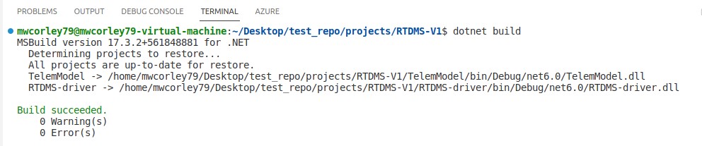
VSCode: RDTMS Solution folder
If the build command displays errors or warnings, then revist the steps for under "Preparing the code" above. Note: that although the code compiles succesfully on the host, it will not run host because the IoT libraries(Device.Bindings, and Devoce.GPIO) target Raspberry Pi hardware (i.e., the GPIO header etc.). Therefore, we need build the code for the Rasberry Pi architecture (ARM), and deploy it to the Raspberry Pi.
To run/test the RTDMS code, it must be deployed to target device. For RTDMS, the target hardware is the prototype device you assembled on the full size breadboard and connected to a Raspberry Pi using the GPIO header.
Prior to deploying the code, you need to specify a target deployment folder on the remote (raspberry pi) device. Open a terminal, and start an ssh session to the device as shown in command below:
            # substitute "username" with raspberry pi username, and "ip-address" for IPv4 address
            # of the raspberry pi
            ssh username@ip-address
Supply the password to authenticate (or consider setting up "passwordless ssh" as mentioned below).
Create remote deploymemt folder over ssh
RTDMS code deployment to Raspberry Pi can be accomplished using two commands that can saved to a script, and run when updated source needs to be uploaded the to the Raspberry PI.
Commands:
Note: Although self contained deployments result in a larger set of files, and
bigger deployment footprint to copy to the target device, it also greatly simplifies
deployment portability, since the runtime and all of the dependencies required to run the
application are packaged together. Self contained deployments are the basis for
packaging using docker (container) images.
Using the deployment commands described above, create a bash scripted named: deploy-script.sh in
"RDTMS_driver/". Copy and Paste the
content shown below, and save the file.
Make the deployment script executable:
chmod +x ./deploy-script.sh
Note: if you installed the 32-bit version of Raspberry PI OS, then you will be need
to the change the commands below to compile for 32-bit, rather 64-bit as ist shown. Specifically,
change the instances of linux-arm64 to
        # 1. Compile for the ARM (64-bit) architecture, and publish the RTDMS-driver to folder:
        # "bin/Debug/net6.0/linux-arm64/publish" for deployment to RPi target device
        dotnet publish --sc -r linux-arm64

        # 2. secure copy from the publish (deployment) folder to the specified (remote) folder on the Raspberry Pi.
        # Replace "username" with your Raspberry Pi username, and "ip_address" with
        # the IP address of your Raspberry Pi. This example assumes a deployment folder named:
        ~/RTDMS_deployment
        scp bin/Debug/net6.0/linux-arm64/publish/* username@ip-address:~/RTDMS_deployment
Note: You might consider configuring your Raspberry PI to use passwordless SSH (see the following link)
https://danidudas.medium.com/how-to-connect-to-raspberry-pi-via-ssh-without-password-using-ssh-keys-3abd782688a
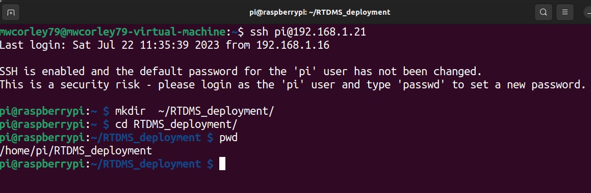
Open a terminal, start an ssh session with Raspberry Pi (if the ssh session used for the deployment section above is still valid,
use that, otherwsie start a new session).
Navigate to the deployment folder (~/RTDMS_deployment), make the RTDMS driver executable, and run the execuatble
as shown in the screen shot illusrated below. The RTDMS driver menu shoud be displayed in the terminal (Console) window:
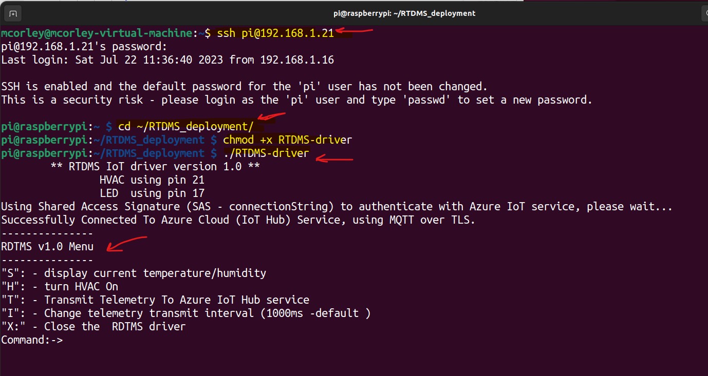
Run the RTDMS driver execuable from ssh session to the Raspberry Pi
The primary intent of the coding exercises is to expose newcomers (systems engineers and cyber security analysts)
to the foundational architectural ideas behind a moderately complex end-to-end IoT system.
Understanding the software that drives an IoT system with architectural perspective is arguably
the most significant aspect for reasoning about critical issues including cyber security, resilency, and system
robustness.
You will find that the majority of the code for this project is provided.
The goal is influence the reader to make a detailed study of the code proivided by completing the exercises to gain
a deeper understanding of how IoT devices functional in the basic general sense. The project code is self guided
walk thru of the design and the implementation of the major components from scratch. The intent is not focus exclusively software
design principles, but rather to guide the reader into holistic architectural perspective of basic IoT systems in general,
while gaining insigns into the some of core implentations concepts and underpinnings required for effective reasoning.
Note: The project is designed around the C# .Net
development stack toolset, and Azure Cloud ecosystem, but other development and stack can easily be substituted. Having
completed this project as is, you might choose to subsitute the .Net C# language for Python or Java,
and Micrsoft Azure Cloud servuices for Amazon (AWS) Cloud services.
Note: The Rasberry Pi is single board computer (SBC), in contrast to a microcontroller in which
the code (i.e., the firmware) is flashed to the deviceand runs as single process executive rather, not as a
full fledged OS process.
The goal of thsi section is enable you
Open source code RTDMS.cs in RDTMS_driver/src
Locate, and complete the functions with the preceding comment:
/* complete this function */
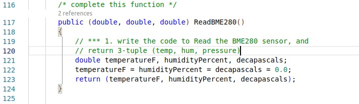
Locate and complete this code in RTDMS.cs
a. Complete the function shown above, by writing the code to read the BME280 sensor, and
return a 3-tuple (temperature, humidity, pressure).
b. Save and deploy the changes to the Raspberry Pi.
c. Run the RTDMS driver, type 's' menu option, press Enter. The output result should resemble
the following screen shot illustrating the BME280: temperature, and humidity data. (Note: only
only the temperature and humidy and displayed, since RTDMS does not currently utilize barometic
pressure).
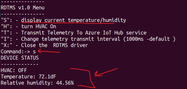
Correct Output for coding exercise #1
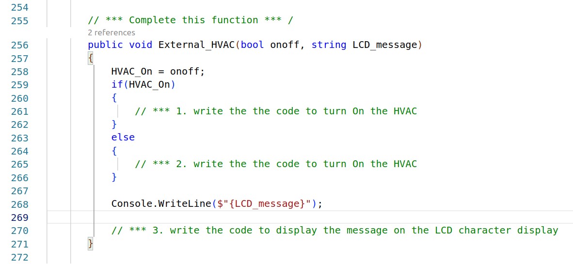
Locate and complete this code in RTDMS.cs
a. Complete the function (shown above), by writing the code activate/deactivate
(turn on and off) the external HVAC system.
Note: Activating The HVAC, should cause the LED controlled by the relay to illuminate (see Figure 1)
If the rely is setup to control an external circuit (e.g., 120v AC), whatever device is attached to the circuit
should activate/deactivate accordingly (i.e., the HVAC system).
Correct Output for coding exercise # 2
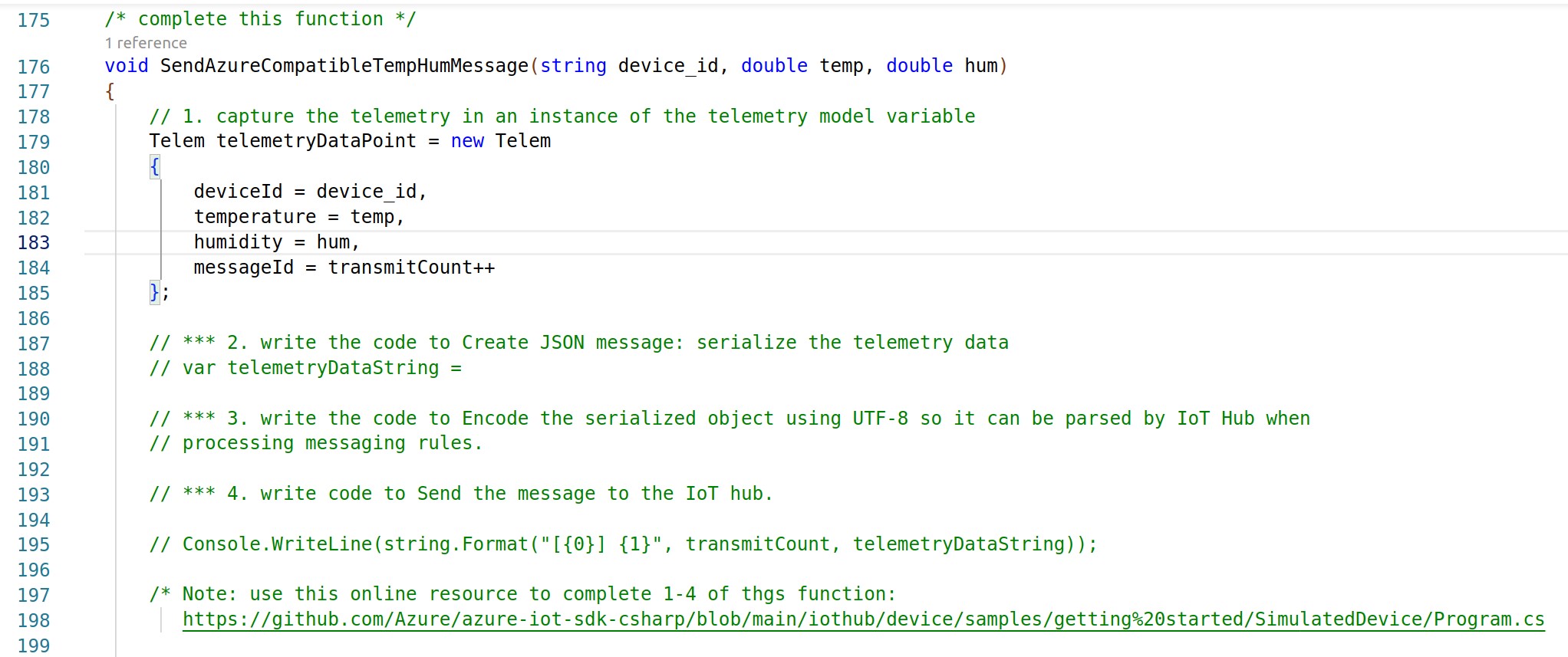
Locate and complete this code in RTDMS.cs
a. Complete the function (shown above). Refer to comments in code above, and write
the code to serialize the telemetry data object as JSON message. Encode the JSON message using UTF-8 encoding,
and finally send the message to the Azure IoT using Message Queuing Telemetry Transport protcol (MQTT).
Use the following URL and guide for this exercise:
https://github.com/Azure/azure-iot-sdk-csharp/blob/main/iothub/device/samples/getting%20started/SimulatedDevice/Program.cs
Note: MQTT communication with the Azure IoT Hub is facilated through the IoTHubClient object. You do not need to establish
an explict MQTT session since, the RTDMS driver establish a secure connection to the IotT Hub service on
during start up.
b. Save and deploy the changes to the Raspberry Pi.
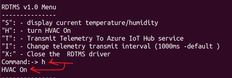
Run the RTDMS driver, toggle 'h' menu option (pressing Enter) to see view the HVAC On/Off function
of the relay activating and deactivating the external device.
The output result should resemble
the following screen shot illustrating the status message: "HVAC On" and "HVAC Off" in the Menu console, and
the LCD character display.
Correct Output for coding exercise # 2
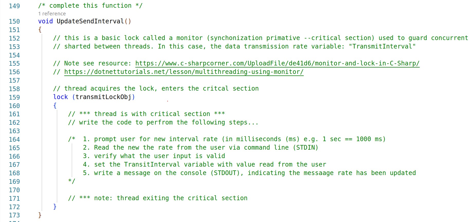
Locate and complete this code in RTDMS.cs
a. Complete the function (shown above). Write the code change the telemetry transmit interval. Referring to
the code shown, implement the following:
a. Prompt user for new interval rate (in milliseconds (ms) e.g. 1 sec == 1000 ms)
b. Read the new the rate from the user via command line (STDIN)
c. Verify what the user input is valid
d. Set the TransitInterval variable with value read from the user
e. Write a message on the console (STDOUT), indicating the messaging rate has been updated.
f. Save and deploy the changes to the Raspberry Pi.
Run the RTDMS driver, select 't' menu option (pressing Enter) Separe thread
of the relay activating and deactivating the external device.
The output result should resemble
the following screen shot illustrating the status message: "HVAC On" and "HVAC Off" in the Menu console, and
the LCD character display.
Correct Output for coding exercise # 2
Azure Functions is a serverless FaaS (function-as-service) solution in which a small unit of source code (using any programming language) is deployed and executed (using triggers), and without requiring explicit IT infrastructure and server management. In the case of the RTDMS prototype, the task is to write a function that will be triggered whenever telemetry (temperature and humidy) data arrives at the IoT hub service (IoT Hub trigger). The function requirements are to process incoming telemetry by deserializing UTF8 encoded messages and extracting the temperature and humidy data, and comparing the data values to user specified thresholds (threshholds can be hard coded). If temperature and/or humidy thesholds are exceeded, the function should send a remote cloud-to-device (c2d) message back to the RTDMS device to automatically (remotely) activate the external HVAC system (note: HVAC system is a 120v AC powered Fan). The LCD character display should be illuminated to indcate HVAC (ON/OFF status). Additionally, the function should use an FTTT web hook to automatically notify an operator by dispatching an email and/or a text message indicating current (exceeded) temperature conditions. You will need to create and IFTTT account to create a web hook. You can learn more about IFTTT here: https://ifttt.com/explore
Prerequisites: An active Azure subscription is required to complete this task. If you have not already
created an account and subscription,
please do so before proceding with this task: https://azure.microsoft.com/en-us/free/students/
Azure Portal Sign in
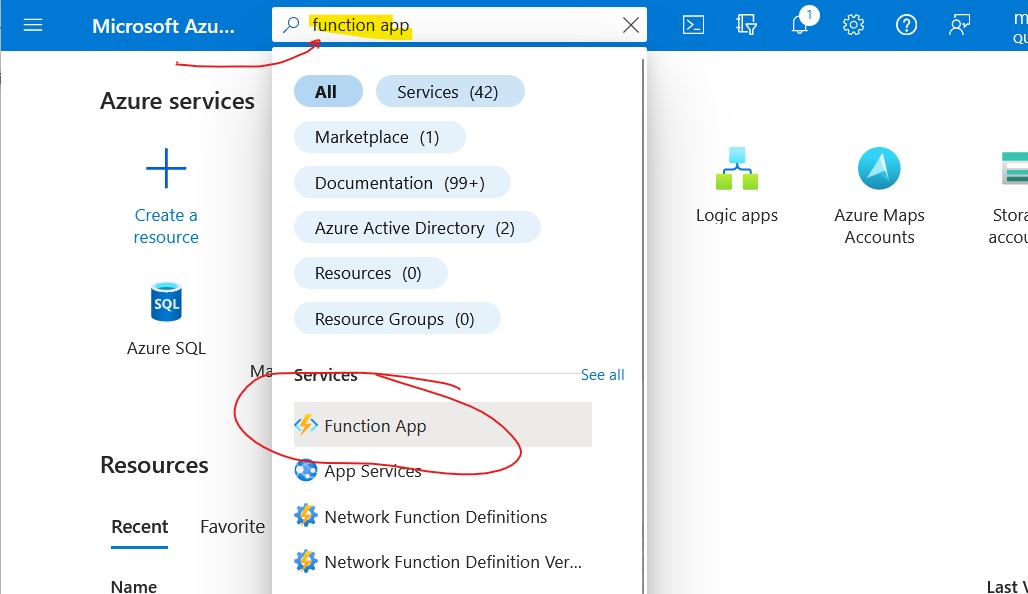
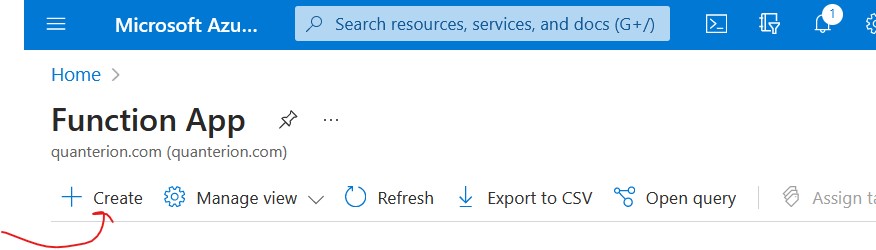
Portal search for Azure Function App
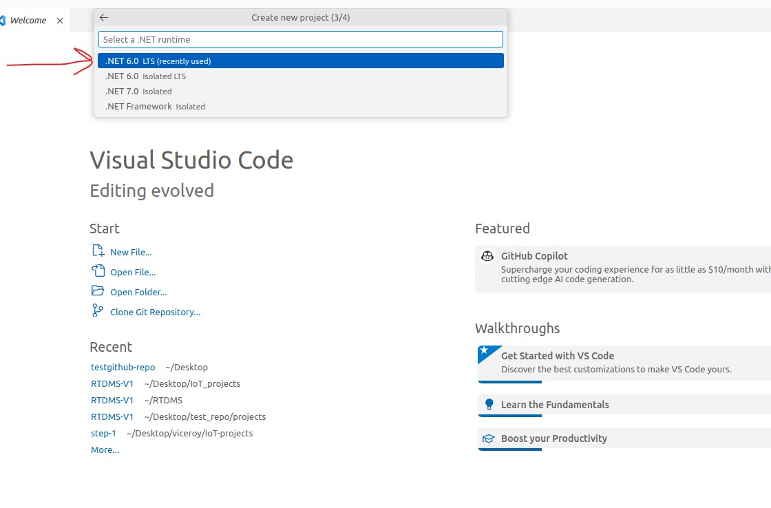
Important: Make sure the runtime version selected for the function app matches the runtime version
selected
for function code project in the next step.
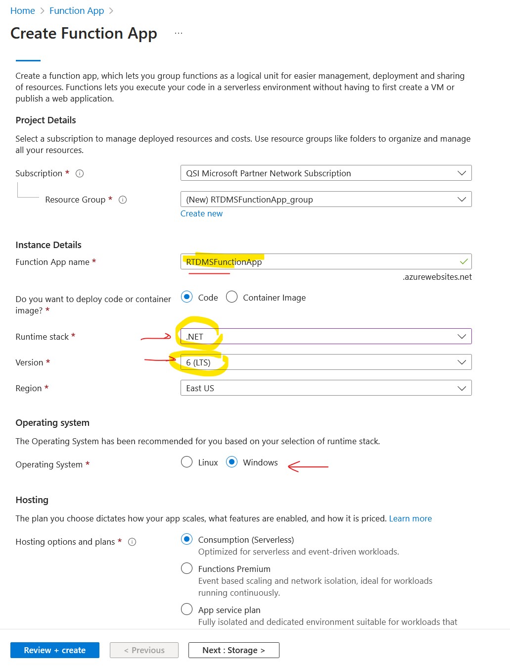
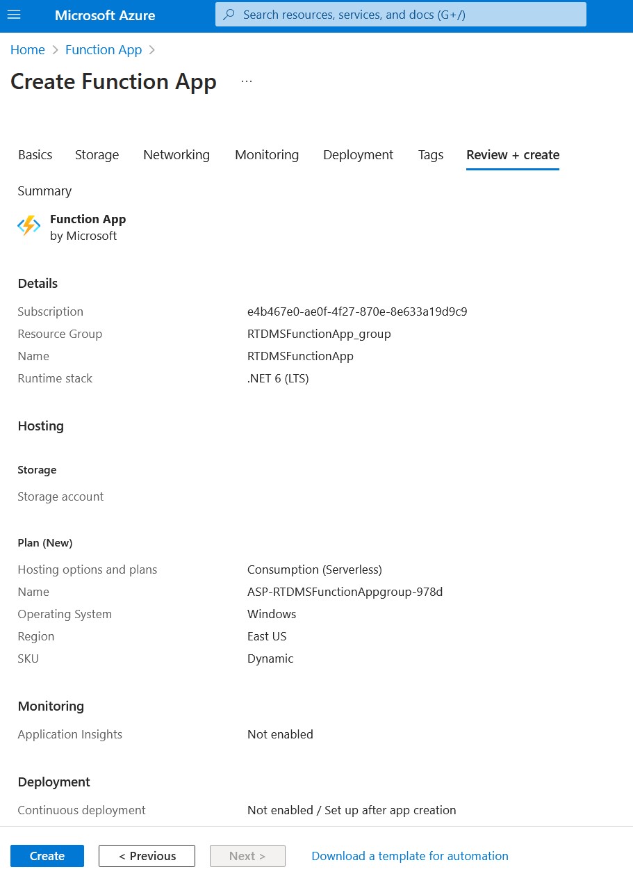
Create an Azure Function Application
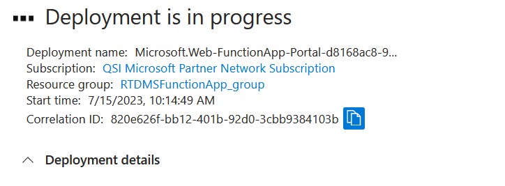
Note: deployment will take a few minutes to complete
Create and Deploy the Function Application
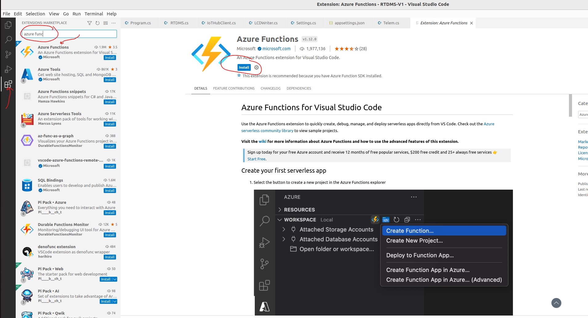
Install VScode Azure Function Extension
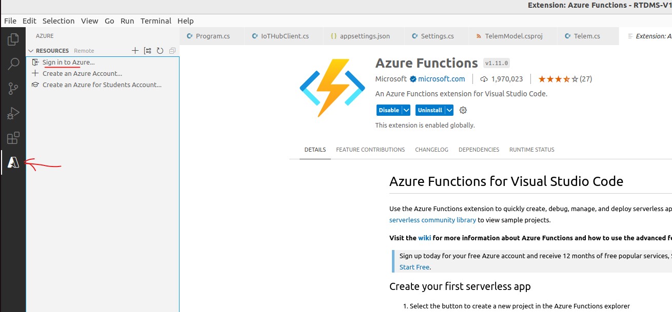
Sign in to azure
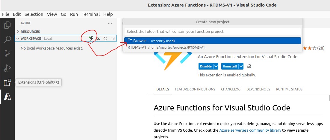
Create a new Azure Function using Azure->Workspace
Create A New Project Workspace Folder
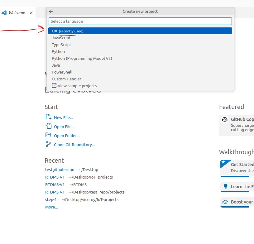
Select C# Language for the Function project
Important: You must use the exact runtime for the function project, and the corresponing Azure
function application
for successfull deployment. Otherwise, you may see a runtime error in the Azure portal
Creating
Azure Functions Reference
Select C# Language for the Function project
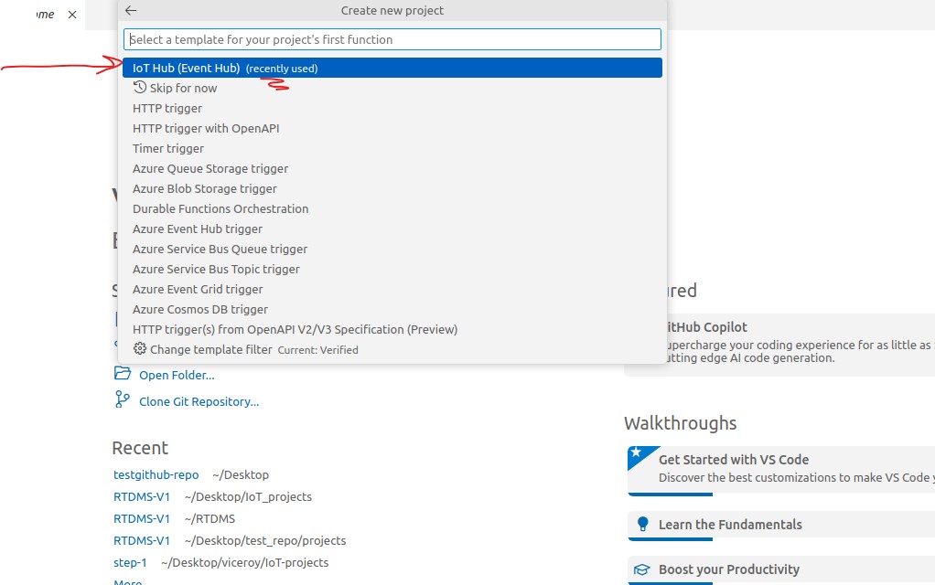
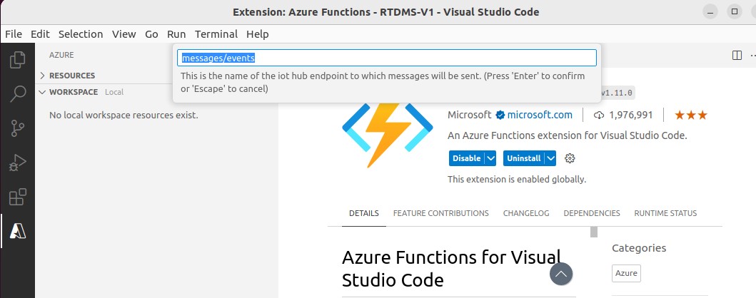
IoT Hub (Event Hub) Trigger
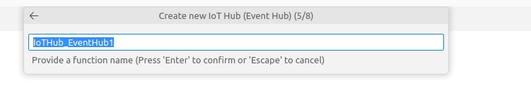
Default function name: can be changed to a name of your choice
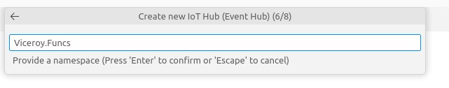
Use namespace, "Viceroy.Funcs", as shown above
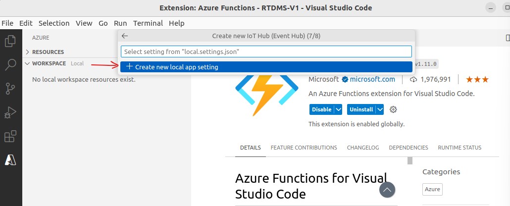
local app settings: "local.settings.json""

Generated Function (source code)
We need to finalize the configuration settings, and make minor modifications to the function copde in order the function to compile, and deploy successfully.
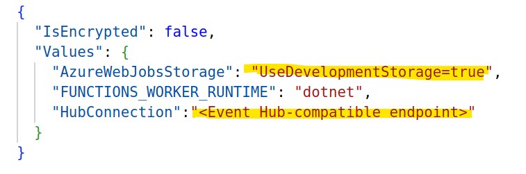
local.settings.json
11.1 In RTDMS_functions explorer view, open "local.settings.json" and update the key: "AzureWebJobsStorage" with the value: "UseDevelopmentStorage=true", and shown above
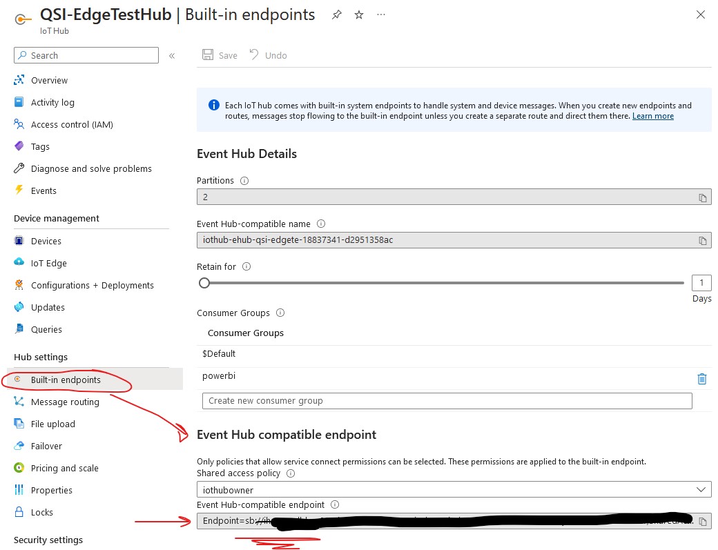
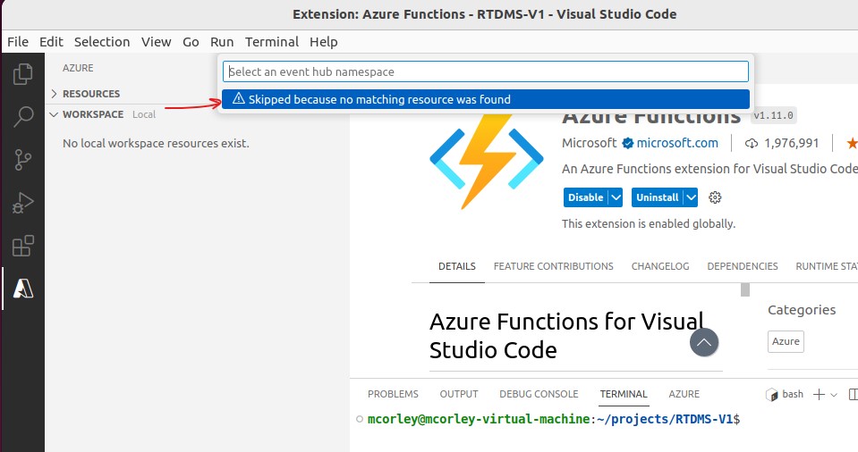
IoT Hub - Event Hub-compatible endpoint
11.2 To get telemetry to pass from the IoT Hub to the function, we need to configure the function with
IoT Hub endpoint for the data to be visible to the function code.
Sign into the Azure portal and navigate to the IoT Hub resource you created
previously.
As shown above, from the left pane menu, click "Built-in
endpoints",
and copy the value for the "Event-Hub compatible endpoint" and paste it as the value
for the
"HubConnection" key in "local.setting.json"
Make sure the keys/values and are double-quoted as shown in the illustration above. Save and close the
file.
11.3 Using Azure portal, navigate the Azure function application: "RTDMSFunctionApp", created in the previous section. Click on Configuration as shown below.
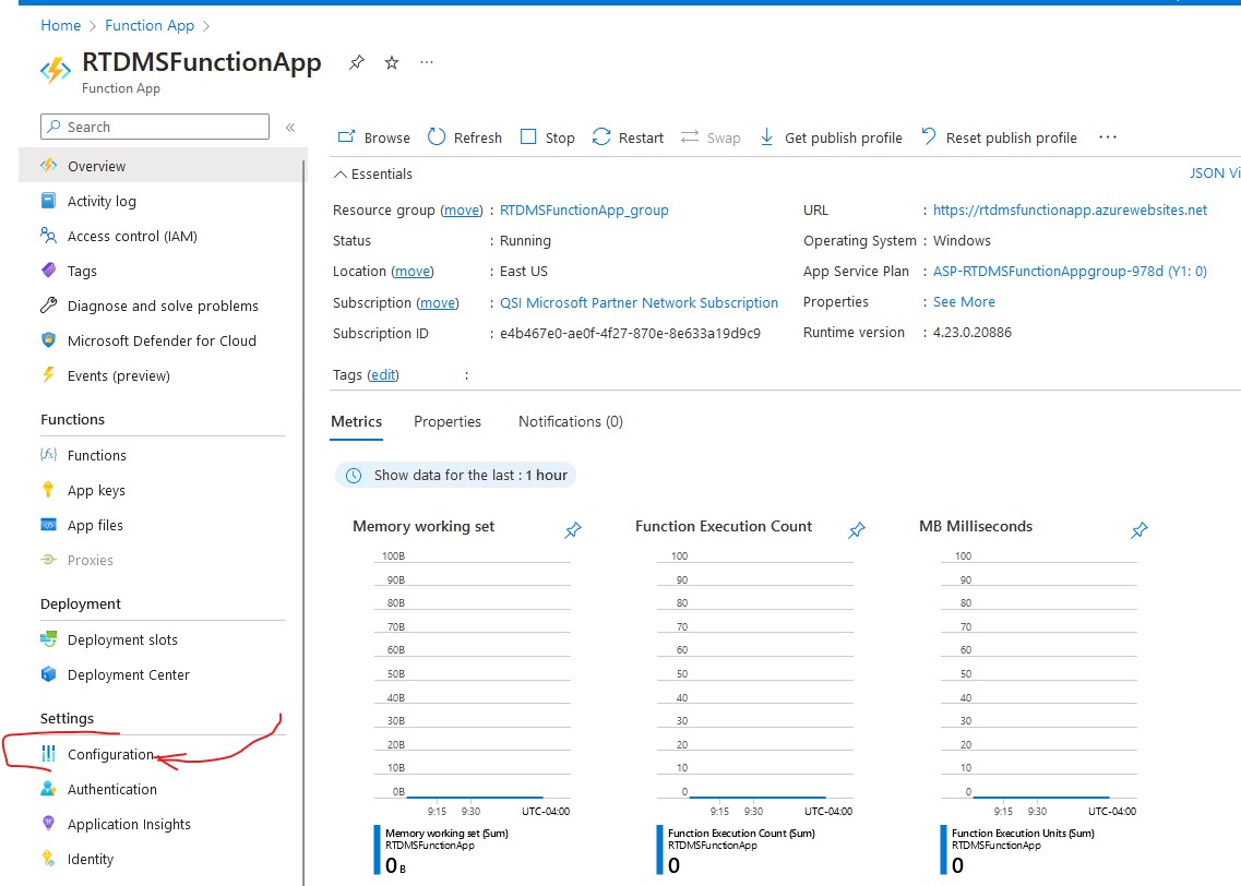
Azure Function App Configuration
Click New application setting and enter the "HubConnection" configuration key, and the "Event-Hub compatible endpoint" of IoT Hub as just as was specified in local.settings.json. This creates an environment variable ("HubConnection") that connects the "RTDMSFunctionApp" function application to the IoT Hub service using the hubs endpoint with the "iothubowner" shared access policy.
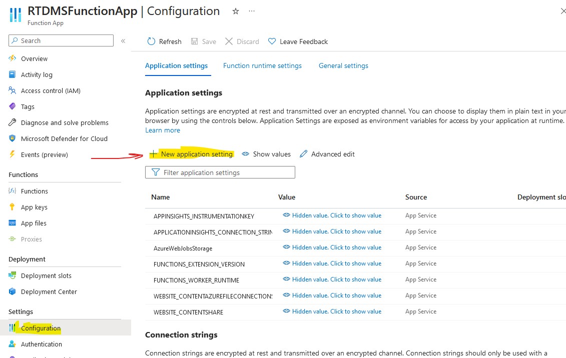
"Azure Function App Configuration
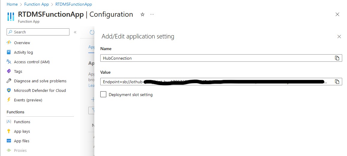
Azure Function App Configuration
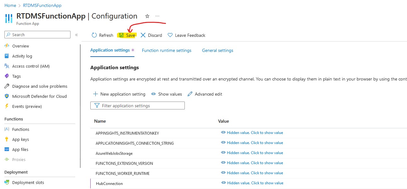
Save Configuration Settings
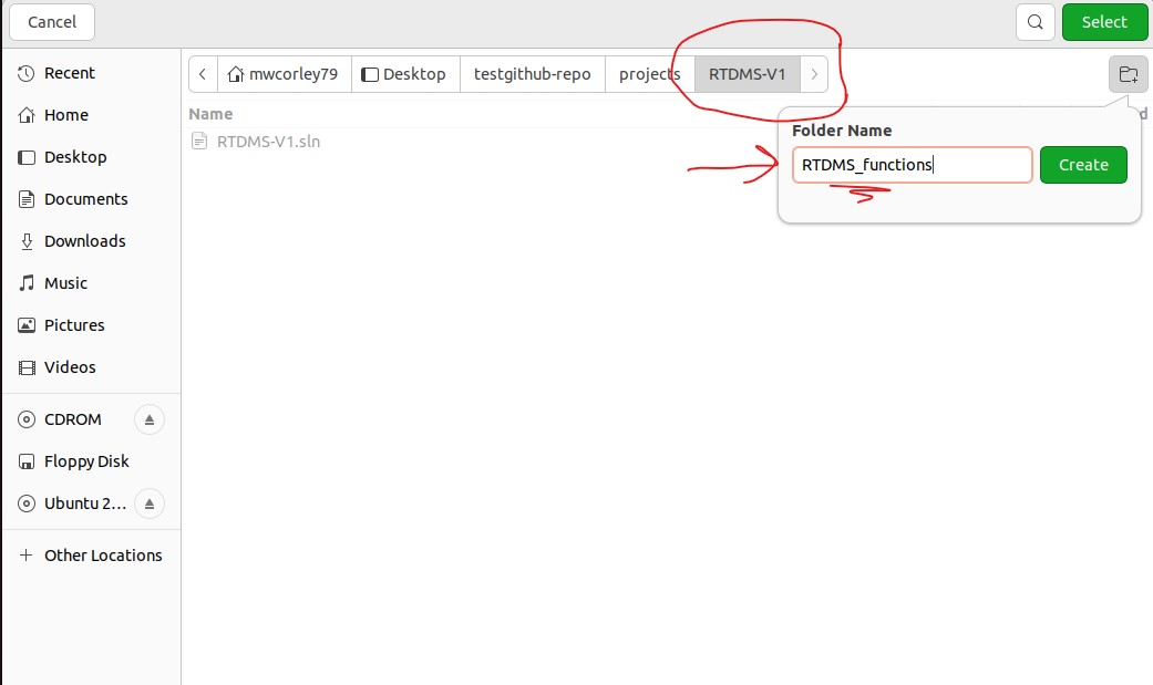
Open a VScode terminal, and navigate to the "RDTMS_functions" project workspace:
Run the folowing commands on the "RDTMS_functions" projects:
            # make sure current folder is the RTDMS project workspace
            cd ~/projects/RTDMS-V1/RTDMS_functions/

            # update the function to use the latest version of the Microsoft.Azure.WebJobs.Extensions.EventHubs package
            dotnet add package Microsoft.Azure.WebJobs.Extensions.EventHubs

            # since the function will have send cloud-to-device (c2d) commands to activate the HVAC system,
            # Add the NuGet package for the c2d communication to function project:
            dotnet add package Microsoft.Azure.Devices

            # The function decodes, and processes device telemetry so add a reference to TelemetryModel class lib project:
            dotnet add RTDMS_functions.csproj reference ../TelemModel/TelemModel.csproj
Make the following updates the function workspace source code: see the screenshot below.
1. Modify the "using Microsoft.Azure.EventHubs;" to "using Azure.Messaging.EventHubs;" consistent with the updated Microsoft.Azure.WebJobs.Extensions.EventHubs package.
2. Update the IoTHubrigger attribute value to use HubConnection setting: "Connection=HubConnection"
3. Modify "message.Body.Array" to "message.Body.ToArray()"
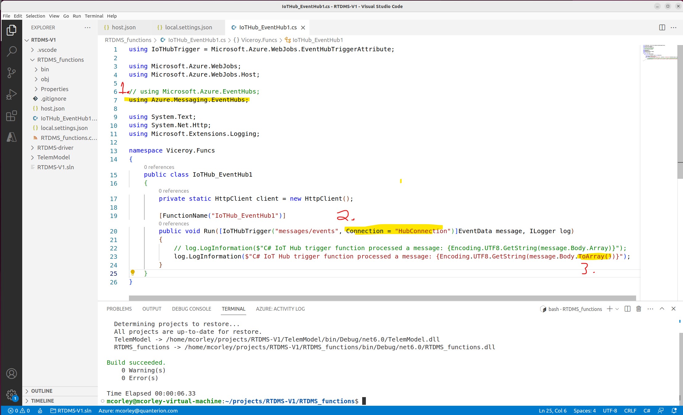
Minor updates to the function project source code
Deploy the Function project to Azure Function Application running in the Cloud by clicking the Azure Icon in the activity bar,
selecting the function workspace, and clicking the cloud-arrow icon.
If you are signed in Azure,
a list of function applications to deploy, will be displayed. Select "RTDMSFunctionApp" and click deploy.
(see the screenshot below)
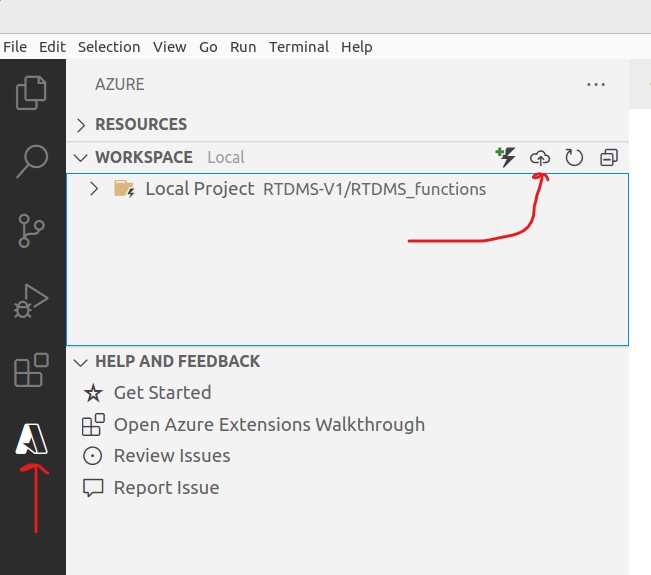
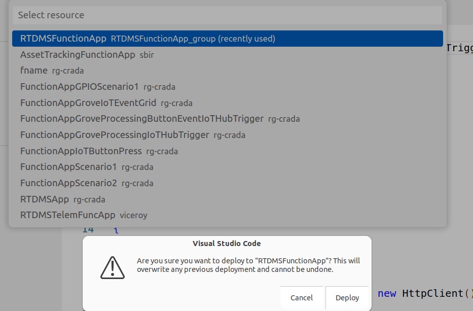
Deploy The Function Project (local workspace) to the Azure Function Application in the Cloud
Use the Azure web portal to navigate the "RTDMSFunctionApp" Function Application. As illustrated below, click the "Functions" option on the side menu to view the deployed function. Note: the function was deployed as zip file package, in read only mode, so you won't be able view the code.
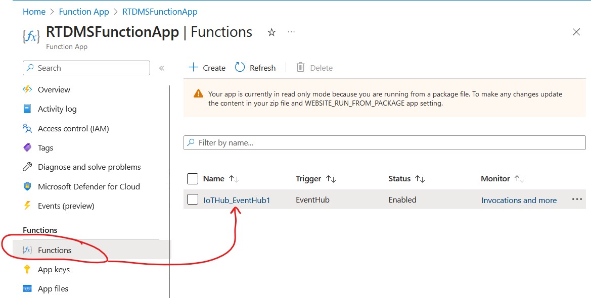
Function Project deployed to the "RTDMSFunctionApp" Function Application
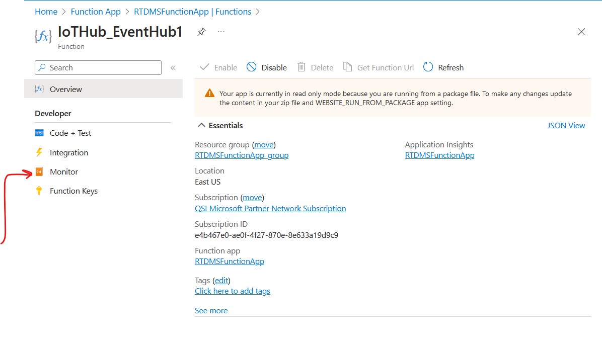
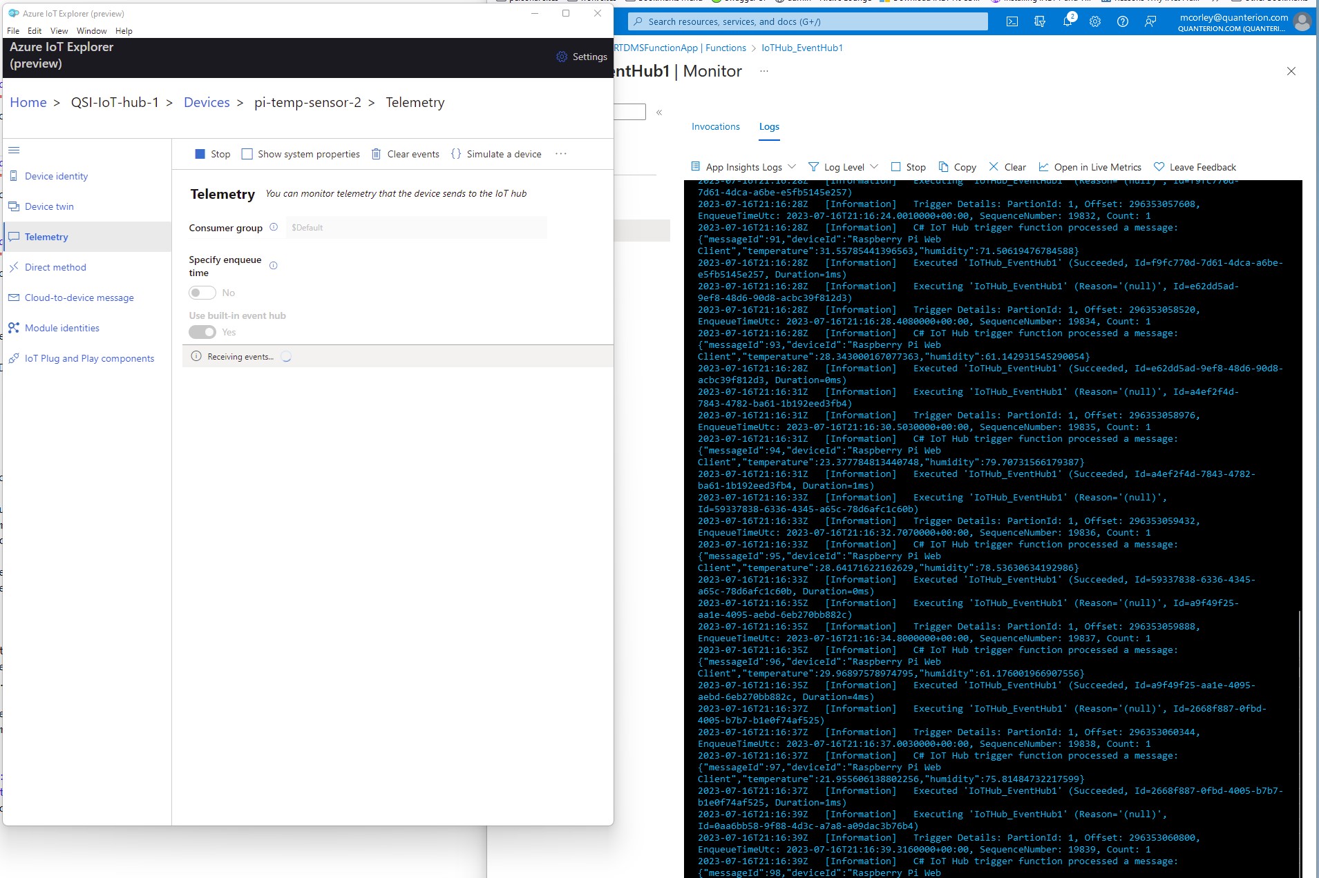
View realtime Telemetry Received by the function
The task is to write a functionto process incoming telemetry by deserializing UTF8 encoded messages and extracting the temperature and humidy data, and comparing the data values to user specified thresholds (threshholds can be hard coded). If temperature and/or humidy thesholds are exceeded, the function should send a remote cloud-to-device (c2d) message back to the RTDMS device to automatically (remotely) activate the external HVAC system (note: HVAC system is a 120v AC powered Fan). The LCD character display should be illuminated to indcate HVAC (ON/OFF status). Additionally, the function should use an FTTT web hook to automatically notify an operator by dispatching an email and/or a text message indicating current (exceeded) temperature conditions. You will need to create and IFTTT account to create a web hook. You can learn more about IFTTT here: https://ifttt.com/explore
Follow the steps in following URL to deploy the web app to Azure Cloud using PaaS deployment model. Once deployed, realtime telemery can be view web browser on a PC or a mobile device. https://learn.microsoft.com/en-us/azure/iot-hub/iot-hub-live-data-visualization-in-web-apps#download-the-web-app-from-github
Azure Cloud-Hosted (PaaS) Realtime Telemetry Monitoring Application
Now that you've completed the development activities you have a better understanding of the device functionality maps into conceptuaal architecture layers: 1. Sensor (Hardware and Software) Layer -> 2. Networks and Gateway Layer-> 3. Data Processing and Analytics (Services) Layer -> 4. Application Layer Perform a critical analysis of the archiecture, identify and document potential vulnerabilties, and implement a mitigation strategy.
This project has hopefully helped you to gain insight and skills implementing, and reasoning about IoT device architectures. Please Note: this project is a work in progress. It is far from complete, and it will be continually refined and improved. Please check back regularly for updates. We also intend to provide repositories that implement this project in Python, C++, and Rust. Please be on the look out for those. Thank you for participating, and I welcome feedback and sugguestions.